What Is UV Water Treatment, and How Does It Work?
UV water treatment disinfects water with ultraviolet light. As water passes through a treatment chamber, germicidal UVC energy damages the DNA or RNA of microorganisms and disrupts their ability to reproduce. The process adds no disinfectant chemicals and works alongside filtration in drinking-water appliances, homes and commercial systems.
The principle is straightforward. Delivering a strong result takes engineering: the light must reach the microorganisms, the water must receive enough exposure, and the reactor must match the actual flow. Agua Topone's model-specific SGS tests show what that combination achieves: more than 99.999% total-coliform reduction in challenge tests using E. coli, with treated-water counts below 1 CFU/100 mL under the reported conditions.
What Happens Between the Water Inlet and Outlet?
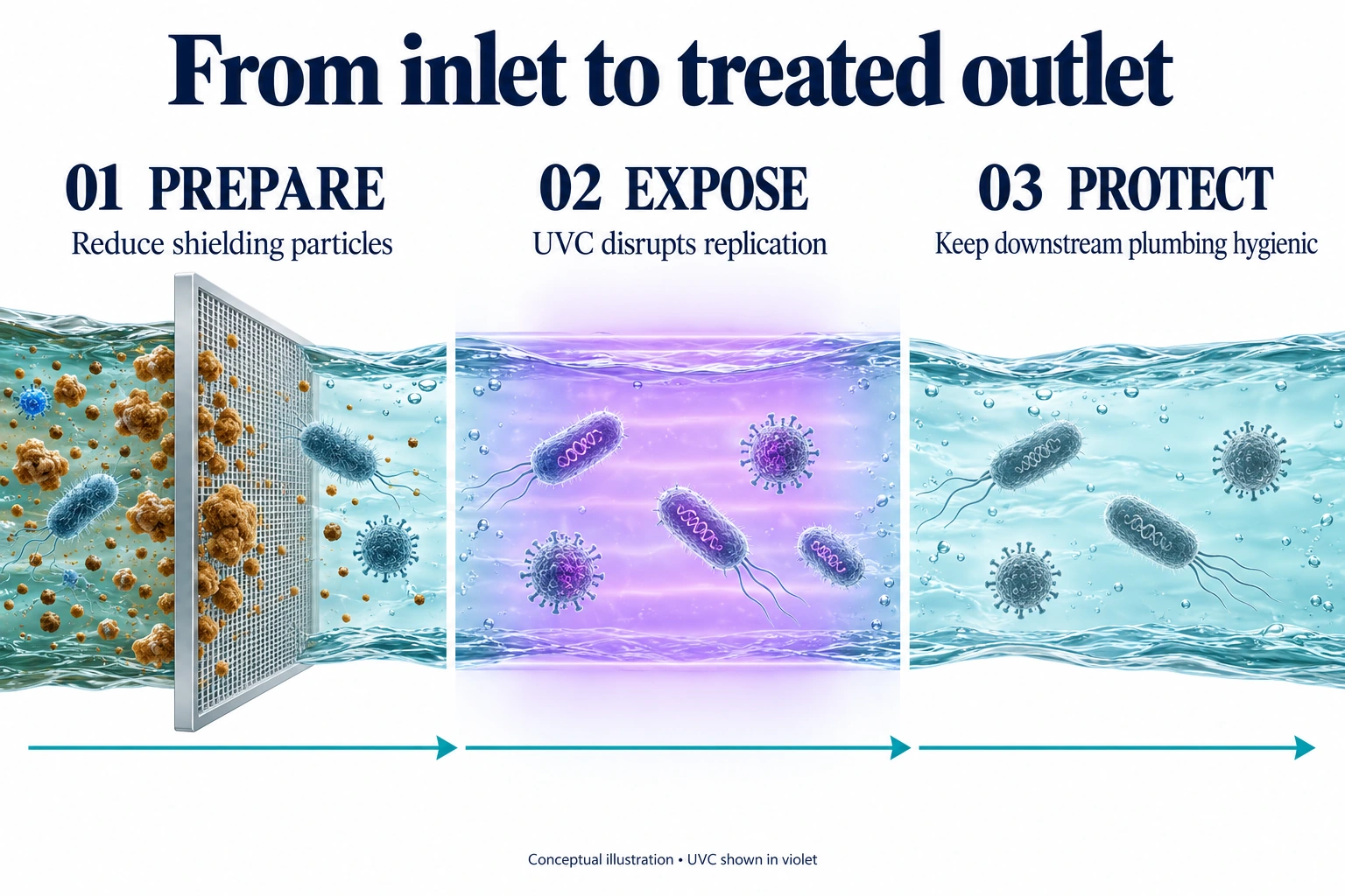
Water is prepared to meet the UV system’s inlet requirements, guided through the treatment chamber, exposed to UVC, and delivered to the outlet. Pretreatment, UV exposure and hygienic downstream plumbing work together, with each stage doing a different job.
A complete UV water treatment system brings together four practical steps:
- Prepare the water. Sediment filtration reduces particles that can shield microorganisms. Depending on the water analysis, the treatment train may also need carbon filtration, iron removal or softening. These stages address different problems; choose them to meet the UV reactor's inlet requirements.
- Guide water through the reactor. The chamber brings water into the UVC treatment zone. Its geometry, internal surfaces and water path determine how light and flowing water interact. In a flow-activated configuration, a flow switch or appliance controller starts the LEDs when demand reaches the activation threshold.
- Deliver the disinfection exposure. The light source, optics and water path work together to supply the required UV dose at the specified flow. Good design addresses the faster and less strongly illuminated paths inside the chamber as well as the average exposure.
- Send treated water to the outlet. Water continues to the faucet, appliance or distribution line. UV adds no continuing disinfectant residual, so clean downstream plumbing and hygienic maintenance help preserve the treatment result.
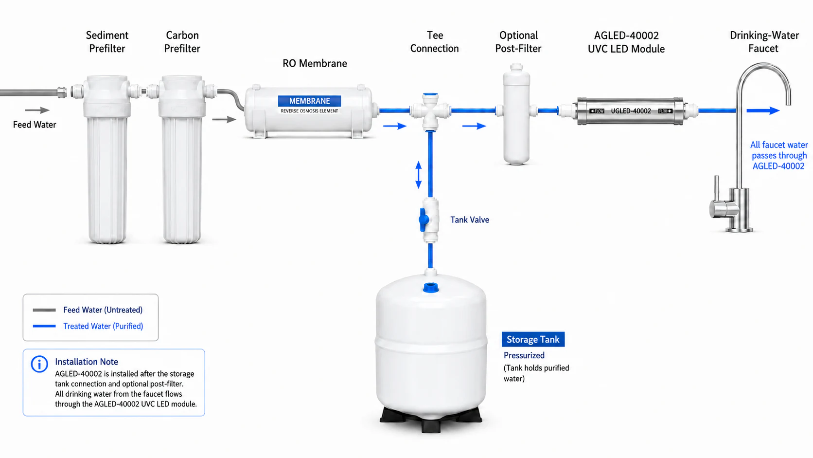
For a tanked RO drinking-water system, a typical final-treatment route is tank-delivery connection → final post-filter → UVC LED module → faucet. The storage tank connects as a branch; the complete plumbing diagram determines the installation. Our RO installation guide explains the arrangement in more detail.
How Does UVC Light Inactivate Microorganisms?
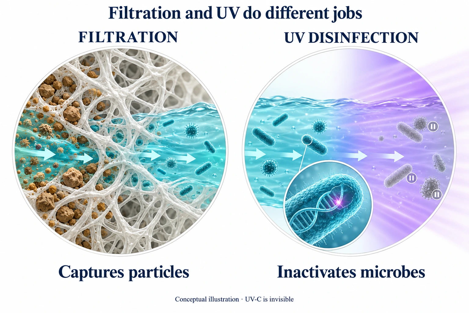
Think of a microorganism's genetic material as its instruction set. UVC energy damages those instructions, preventing normal replication. Unlike a filter, UV does not need to trap the organism to inactivate it.
At the molecular level, DNA absorbs UVC energy and develops lesions, including links between adjacent thymine bases called thymine dimers. RNA contains uracil rather than thymine and undergoes its own forms of photochemical damage. This explains why UV treatment targets biological activity while the inactivated organism can remain physically present in the water.
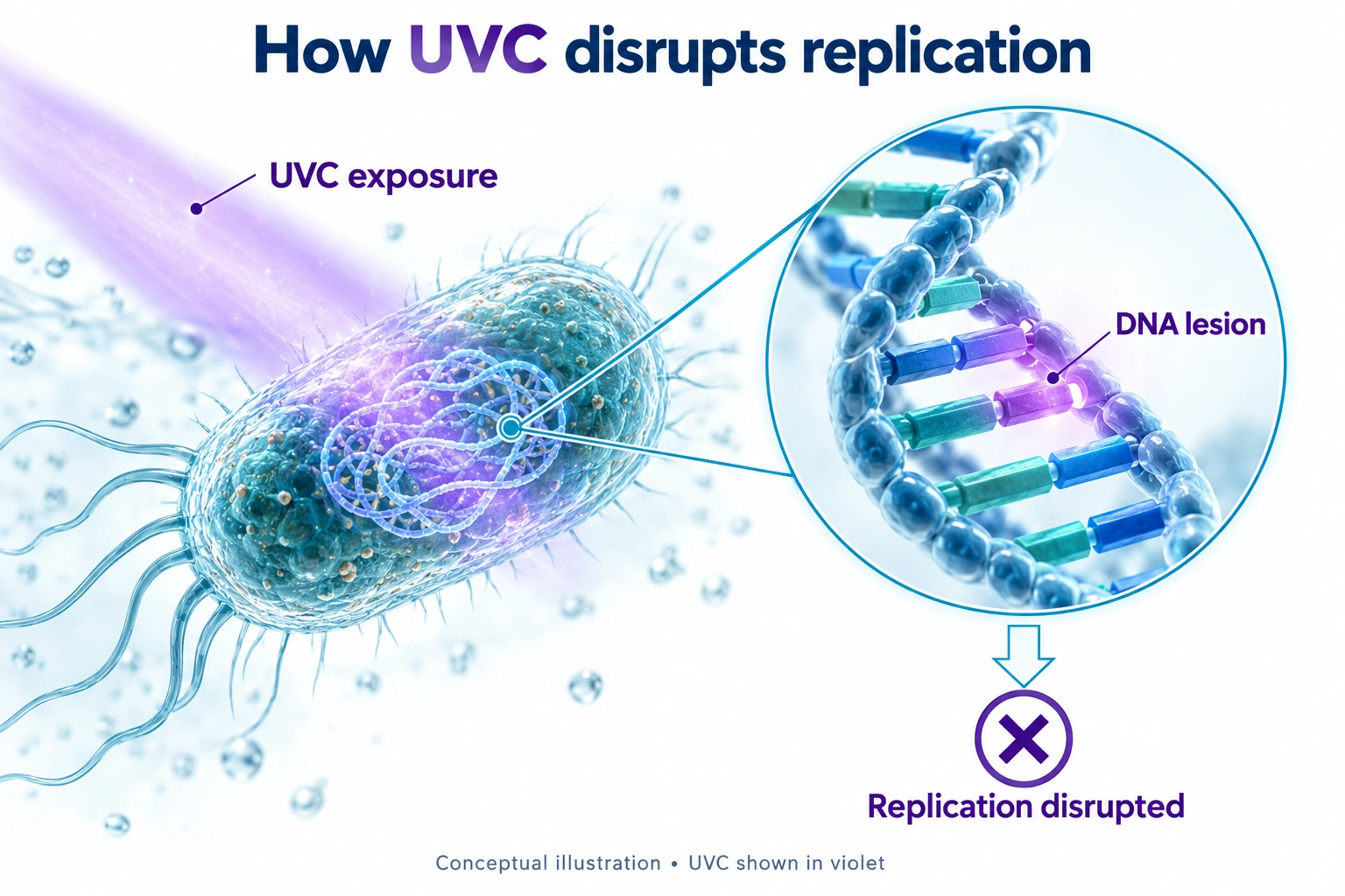
Conventional low-pressure mercury lamps commonly emit at approximately 254 nm. UVC LEDs generate light in a semiconductor; Agua Topone models such as AGLED-40002 and AGLED-40012 specify 270–280 nm. Both technologies use germicidal ultraviolet energy. LEDs also support immediate switching, which suits equipment that dispenses water intermittently.
Water Moves Quickly. How Does UV Still Work?
Flowing water can receive effective UV treatment when the reactor delivers enough germicidal energy during its passage. Exposure time is one part of the calculation; light intensity and the water path also matter. The model’s flow rating, water-quality requirements and microbiological test results connect the design to a demonstrated result.
UV dose: how much germicidal energy reaches the target
UV dose, also called fluence, describes the ultraviolet energy delivered during exposure. Engineers express it in millijoules per square centimeter (mJ/cm²). Under constant, uniform illumination, the basic relationship is:
D: UV dose · IUVC: UVC intensity · t: exposure time
For example, an intensity of 10 mW/cm² over 4 seconds gives 40 mJ/cm². This is an arithmetic illustration, not a measurement from a particular reactor. Inside flowing equipment, light intensity and residence time vary, so engineers confirm performance through optical and hydraulic design plus product testing.
Different microorganisms and reduction targets require different doses. As a product example, AGLED-40012 specifies 40 mJ/cm² at its 12 GPM operating basis. That specification helps define its treatment duty; the separate microbiological report records the measured challenge-test result.
Flow rate: how long water stays in the treatment zone
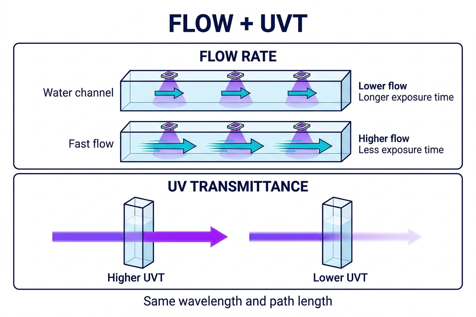
When more water passes through the same chamber each second, the average exposure time generally falls. This is why a system's rated flow matters as much as its light source.
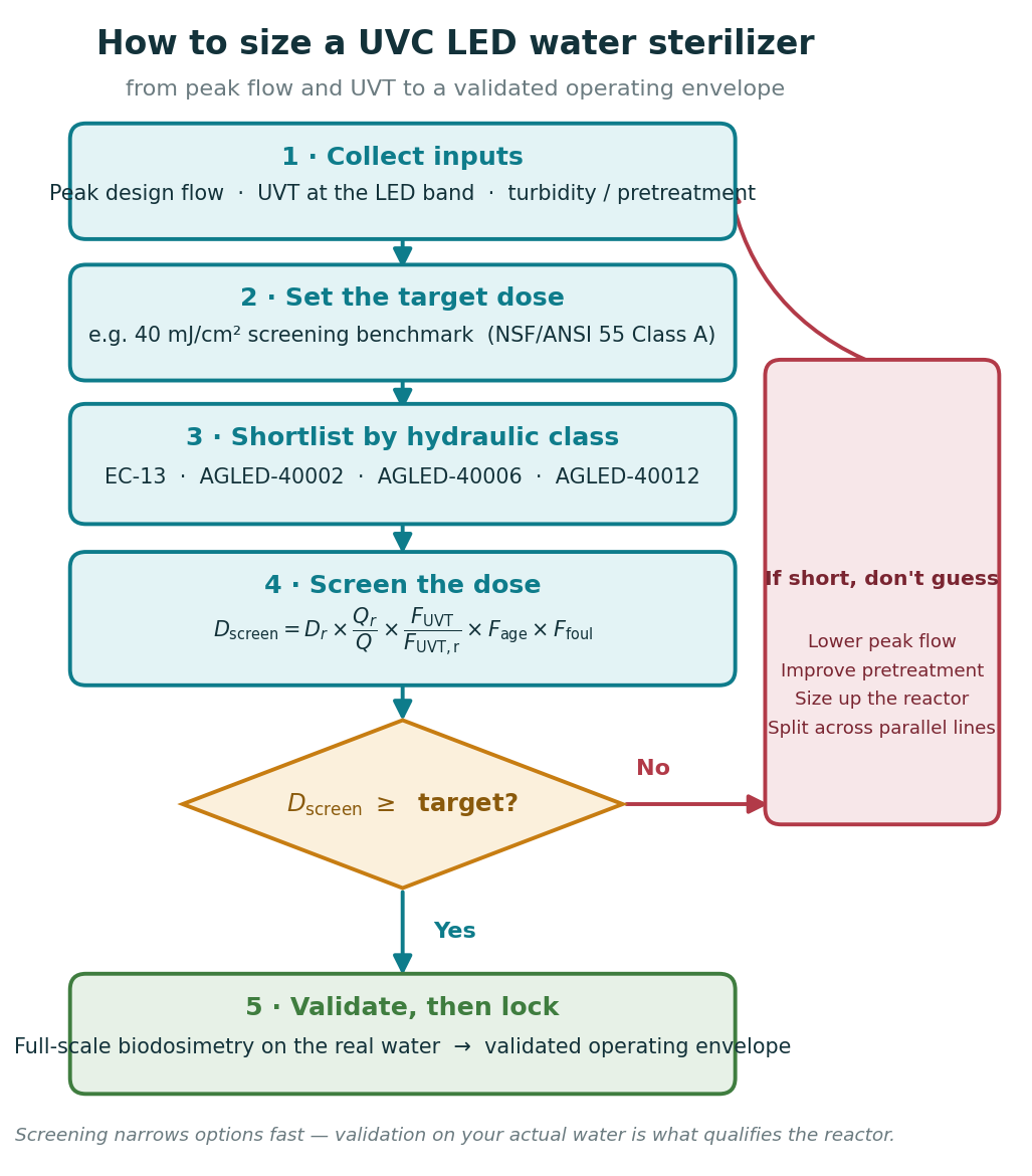
Select against the highest realistic flow, including simultaneous outlets in a whole-house project. A large daily consumption spread across the day creates a different duty from several taps opening together. Flow control helps keep the operating point within the intended treatment range. See our flow-and-UVT sizing guide for the engineering method.
UVT and fouling: whether the light reaches its target
UV transmittance (UVT) measures how much ultraviolet light passes through water at a specified wavelength and path length. Water can look clear while dissolved substances still absorb UVC. Suspended particles can shield microorganisms, and scale or deposits on optical surfaces can reduce light delivery.
For example, the AGLED-40012 specification lists water transmittance above 90%, turbidity below 1 NTU, hardness below 120 ppm and iron below 0.3 ppm. These are model-selection inputs, not additional conditions inferred from the SGS report. Match the actual water analysis to the current model requirements and keep optical surfaces clean. Confirm the UVT measurement wavelength and optical path length when comparing water data with the model requirements. Our UVT guide explains the measurement.
How Agua Topone Turns UVC Light into a Working System
A working water-treatment system brings the light source, reactor and controls together. Agua Topone coordinates the optical path, driver, thermal design and water flow so the product delivers disinfection in its intended application.
Reactor geometry, reflective materials and flow control
What keeps changing water demand within the intended treatment range? Reactor design manages the water path and useful light, while flow control helps keep throughput within the selected operating duty.
Our AGLED-40012 combines a reversing water-flow design with high-efficiency reflective materials, an integrated flow switch and a flow-limiting valve. The water path manages exposure, the reflective surfaces support useful light delivery, and the valve helps control the amount of water passing through the chamber.
Its published UVC radiant output is 2,000 mW, alongside a 50 W rated electrical input. These figures describe different quantities: electrical watts power the complete unit; optical output describes the UVC radiation. Delivered dose and microbiological testing then show how the complete system performs.
Compact, on-demand control for drinking-water equipment
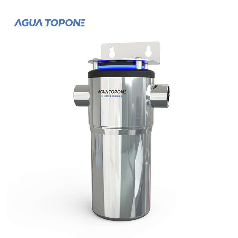
How does UV fit inside a crowded drinking-water appliance? A compact body, quick connections and flow-activated LEDs support integration; the appliance’s dispensing flow still needs to match the module’s activation and treatment range.
For smaller water paths, AGLED-40002 combines a stainless-steel body, 1/4-inch quick-connect ports, 160 mW UVC output and a 4 L/min flow rating. Its flow activation starts above 500 mL/min. Separate 12 V DC and 24 V DC versions let an equipment manufacturer select the supply that fits the appliance.
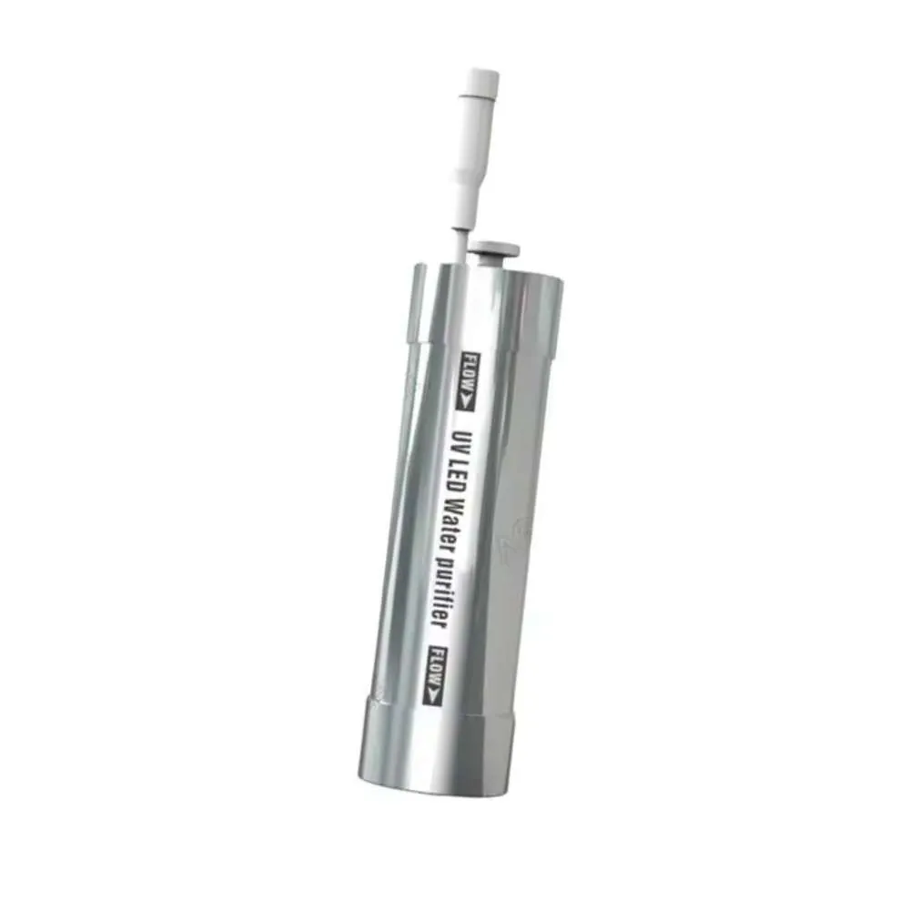
This arrangement supports treatment when water dispenses. Integration still needs a clear control plan: the host appliance's lowest dispensing flow must reach the activation threshold, and its highest flow must remain within the selected treatment duty. AGLED-40002's maximum inlet pressure is 0.8 MPa (8 bar).
Thermal and optical engineering behind the package
What helps the light source keep working effectively? Heat needs a route away from the LED junction, and the optical window needs to transmit UVC into the water. That is where packaging and materials matter.
UVC LEDs generate heat as well as light. Agua Topone's published technology platform uses an aluminium nitride ceramic base with 170–230 W/mK thermal conductivity to carry heat away from the LED junction. Its optical design includes a dual-sided anti-reflective sapphire window with UVC transmittance above 98%.
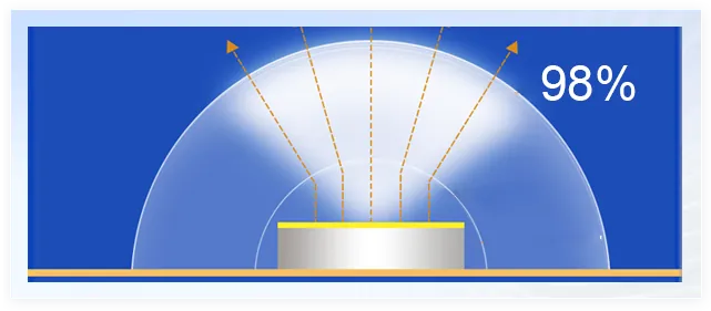
These details explain two practical priorities: remove heat from the light source and transmit more of its useful radiation into the treatment path. They describe component-level engineering; whole-system performance comes from coordinating the selected components with the reactor and operating conditions. Explore our UVC LED technology for more detail.
What Results Have Our Systems Achieved?
In SGS challenge testing, treated-water total-coliform counts fell from millions of CFU per 100 mL to below 1 CFU per 100 mL. Both tests used Escherichia coli ATCC 25922 at the start of operating life. Total-coliform counts were measured using GB/T 5750.12-2023; the challenge-test procedure is identified separately in each report.
SGS NBF25-0016420-01 · 4 L/min · Reported reduction >99.999%
| Tested model | Test flow | Inlet CFU/100 mL | Outlet CFU/100 mL | Reported reduction |
|---|---|---|---|---|
| AGLED-40002 | 4 L/min | 2.4 × 10⁶ | <1 | >99.999% |
| AGLED-40012 | 50 L/min | 2.0 × 10⁶ | <1 | >99.999% |
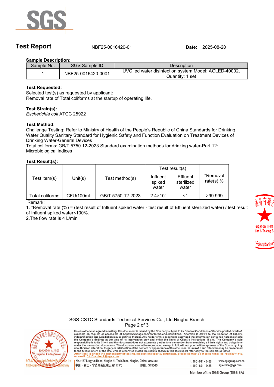
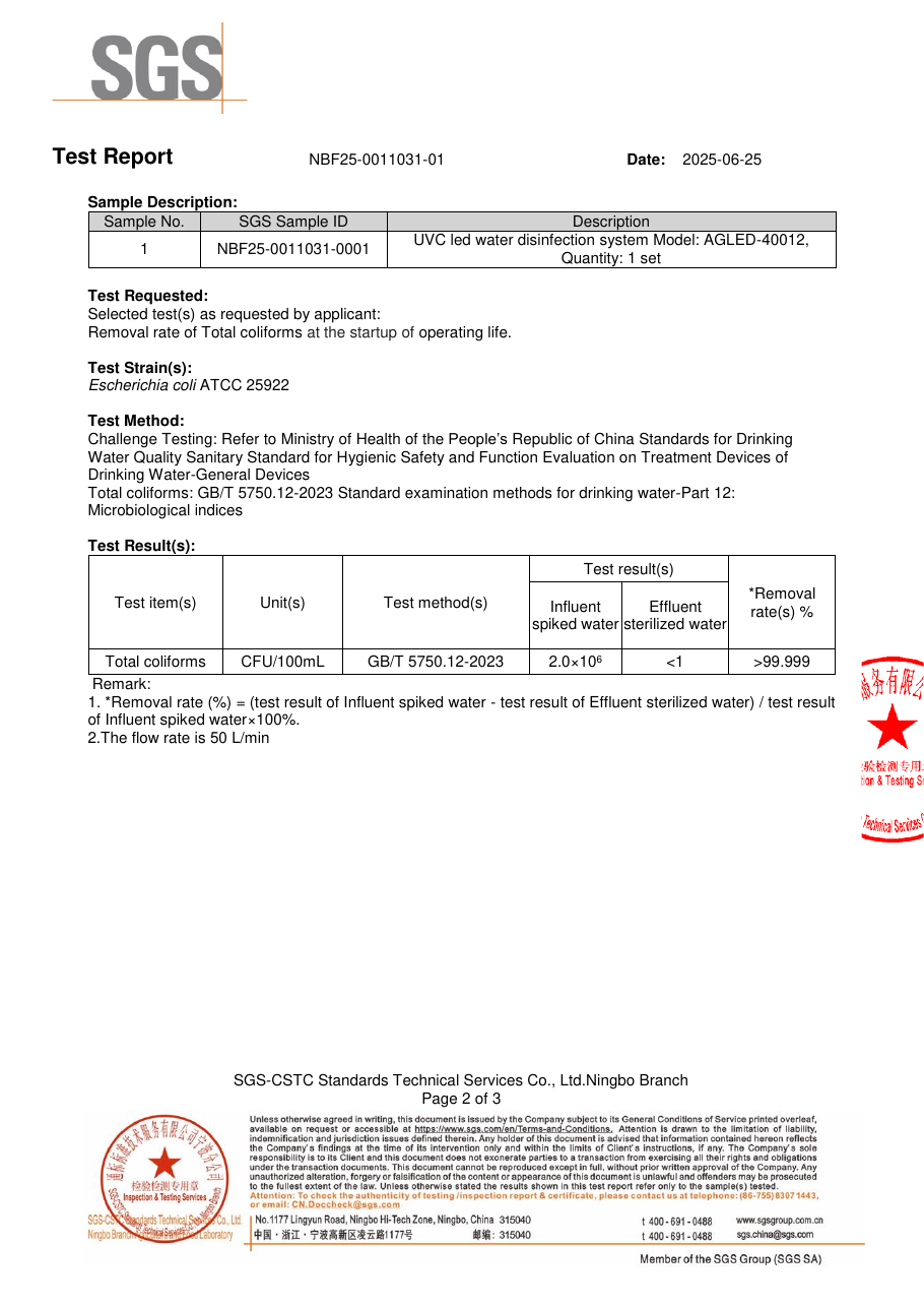
Open the original reports: AGLED-40002 — NBF25-0016420-01, August 20, 2025 and AGLED-40012 — NBF25-0011031-01, June 25, 2025.
For perspective, a 3-log reduction equals 99.9%, 4-log equals 99.99%, and 5-log equals 99.999%. Both SGS reports record more than 99.999% reduction, with outlet counts below the reported 1 CFU/100 mL threshold.
AGLED-40012's SGS test used 50 L/min; its published whole-house product rating is 12 GPM, approximately 45 L/min. For a project with a specific outlet criterion, our team matches the model to the operating conditions and supports verification of the installed outlet. The figures above are laboratory results; the field examples below show actual installation.
From the Test Bench to Real POU and POE Installations
Point of use (POU) treats water for a particular faucet or appliance. Point of entry (POE) treats water on the incoming line to a home or facility. Our field installations show how those two routes translate into practical layouts.
Bulgaria: AGLED-40002 inside an under-sink RO system
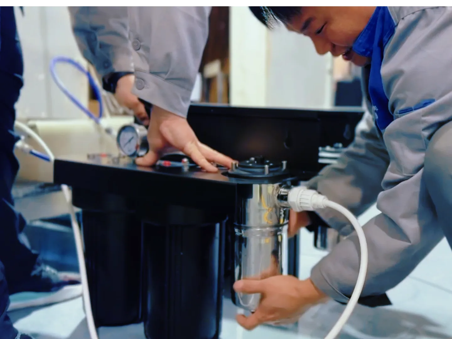
Application and installation. Adding a UV stage to an under-sink RO system means fitting treatment into limited space while preserving access for servicing. In our documented Bulgarian installation, the stainless-steel AGLED-40002 sits above the multi-stage RO assembly. Mounting clips, connected tubing and a visible blue status indicator can be seen in the photograph. The layout uses the cabinet’s upper space and keeps the filter housings accessible.
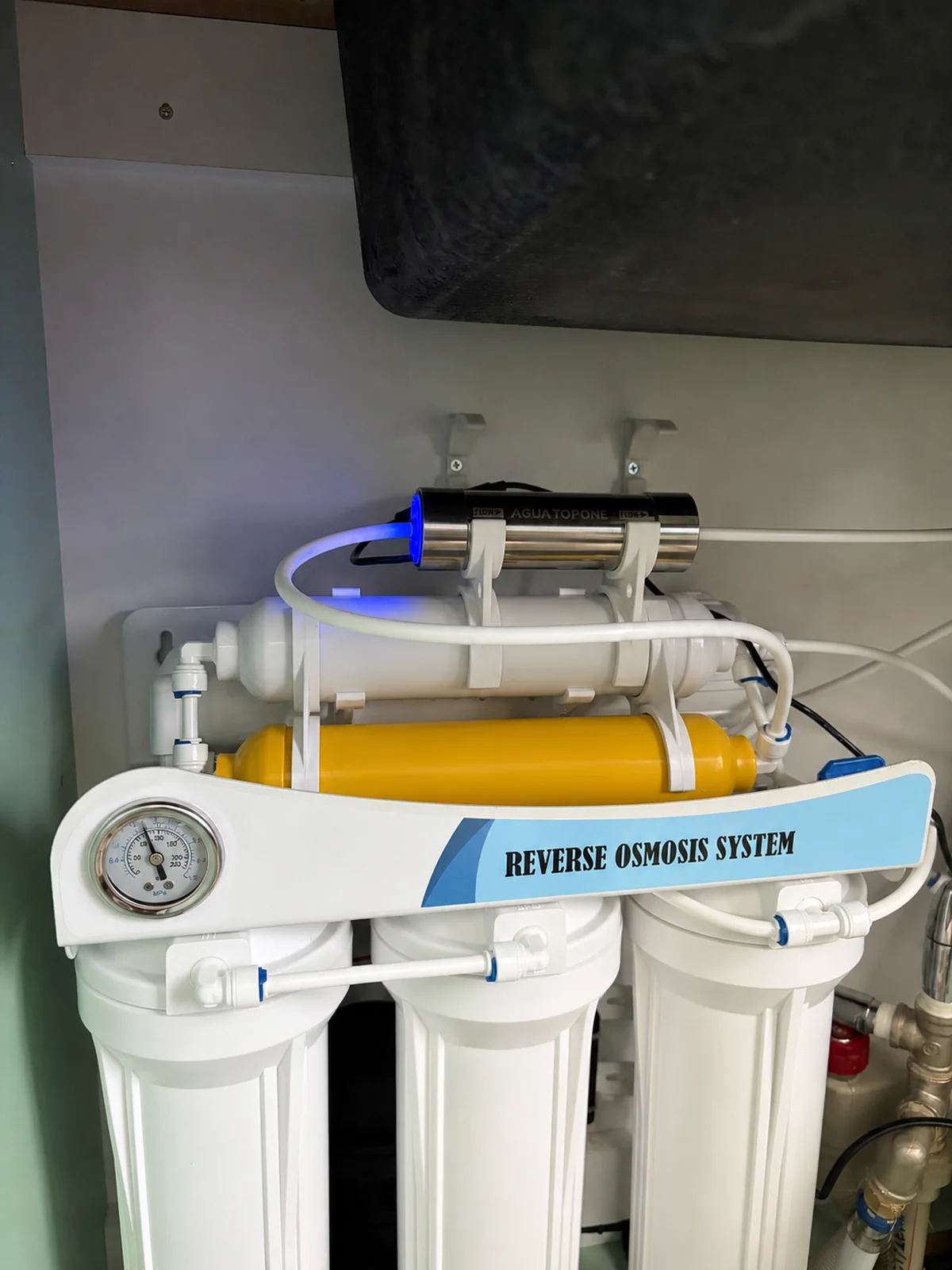
Integration result and model performance. The practical outcome is compact integration into an existing drinking-water system. For a similar project, confirm final-line placement, peak faucet flow, the correct voltage version and room for servicing. The same model’s SGS report provides >99.999% reduction at 4 L/min as laboratory performance evidence. See the complete Bulgarian RO installation.
Other POU options include the EC series, with nominal flow choices from 0.4 to 1 GPM, for suitable dispensers and appliance water paths. The POU application page connects these formats to equipment requirements.
United States: AGLED-40012 on a whole-house well-water line
Application and installation. A whole-house well-water project places the UV stage on the incoming supply and needs accessible connections for service. For a documented U.S. residential private-well project, Agua Topone supplied AGLED-40012 as a whole-house UVC LED stage. The completed installation places the reactor below the copper water line, with a nearby shut-off valve and a separate visible driver.
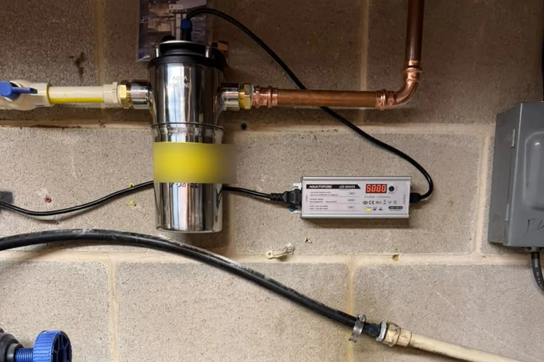
Integration result and model performance. The result is a documented POE installation with accessible connections and service points. The model combines a 12 GPM flow class, 100–240 V AC input and a replaceable UVC LED module. Its driver supports a 5,000-hour operating-time countdown. The model’s SGS challenge test provides the separate treated-water result: more than 99.999% total-coliform reduction at 50 L/min. Read the U.S. whole-house case.
For other incoming-line duties, our range includes the 6 GPM AGLED-40006 and 12 GPM AGLED-12G. GPS and VPS configurations combine filtration with a UVC LED stage. Start with POE system options and select against peak simultaneous demand and water quality.
For centralized supply and pretreated process-water lines, explore our MegaUV industrial UV water treatment systems.
How Do You Confirm the Result After Installation?
Confirm the result by connecting the installed operating conditions to an outlet-water test. Check that peak flow and inlet water quality match the selected model, then verify power, controls and the status indications described in its instructions. A status light shows the condition it was designed to report; it does not by itself measure delivered UV dose. Follow the equipment instructions for commissioning and downstream hygiene, including any required cleaning or sanitation of tubing and outlets. Arrange sampling with a qualified testing laboratory and follow its collection instructions. Compare the outlet result with the project’s required microbial criterion, and keep the model, flow, water-quality and maintenance records with that result. This connects product selection, installation and measured performance.
Frequently Asked Questions
Why add UV if I already have a reverse osmosis system?
A terminal UV stage treats water after storage and post-filtration, close to the outlet. It addresses the microbial risk associated with downstream storage and components alongside the RO membrane’s treatment role. The final water path and installation position must suit the complete system; downstream hygiene and maintenance still matter. See our RO installation guide.
Why might bacteria still be detected after installing UV?
A positive outlet result calls for a check of the complete system. Review equipment operation, actual flow, UVT, optical-surface fouling, downstream plumbing and the sampling procedure. Pre-existing contamination after the UV chamber can affect the outlet even when the reactor operates. Follow the model’s troubleshooting and hygiene instructions, then retest with the laboratory. A single result does not identify which part of the system needs attention.
Can UV switch off when water is not running?
Flow-activated UVC LED configurations are designed for on-demand treatment, with immediate LED switching as the controls detect demand. Follow the selected model’s control arrangement and activation threshold. Do not apply that operating pattern to every UV system: lamp-based equipment may require continuous operation and warm-up time under its own instructions.
Do I still need a filter if I install UV water treatment?
Usually, yes. UV targets microorganisms; filtration addresses contaminants according to the filter's capabilities. UV alone does not remove sediment, hardness minerals, dissolved salts or heavy metals. Suitable pretreatment also helps UVC reach the microorganisms. Our UV disinfection versus filtration guide explains how the stages work together.
Does UV change the taste or temperature of drinking water?
UV adds no disinfectant chemicals and does not depend on heating water to disinfect it. Existing taste and odor problems need the appropriate separate treatment. UVC LEDs still generate heat, so thermal design and operating conditions influence water-temperature changes.
Can a UVC LED water system reduce E. coli by more than 99.999%?
Yes. SGS reports for Agua Topone AGLED-40002 and AGLED-40012 record more than 99.999% total-coliform reduction in challenge tests using E. coli ATCC 25922, at 4 L/min and 50 L/min respectively. Both reports record treated-water counts below 1 CFU/100 mL at the start of operating life under the stated test conditions.
How long does a UVC LED system last?
Service life depends on the model, duty cycle, water quality and thermal conditions. AGLED-40012 specifies a 5,000-hour L70 service basis: L70 marks the point when light output has fallen to 70% of its initial value under defined conditions. Operating hours are different from elapsed calendar time. An LED lifetime, a driver’s accumulated operating-time counter and a maintenance schedule measure different things; check how the selected model records time. Follow its operating instructions and cleaning schedule.
Bring the Water Conditions. We Will Match the System.
Since 2006, Agua Topone has developed water-disinfection products for residential, commercial and equipment-integration projects. Our manufacturing base covers 10,000+ m², with 40+ national patents and experience serving 80+ countries and regions.
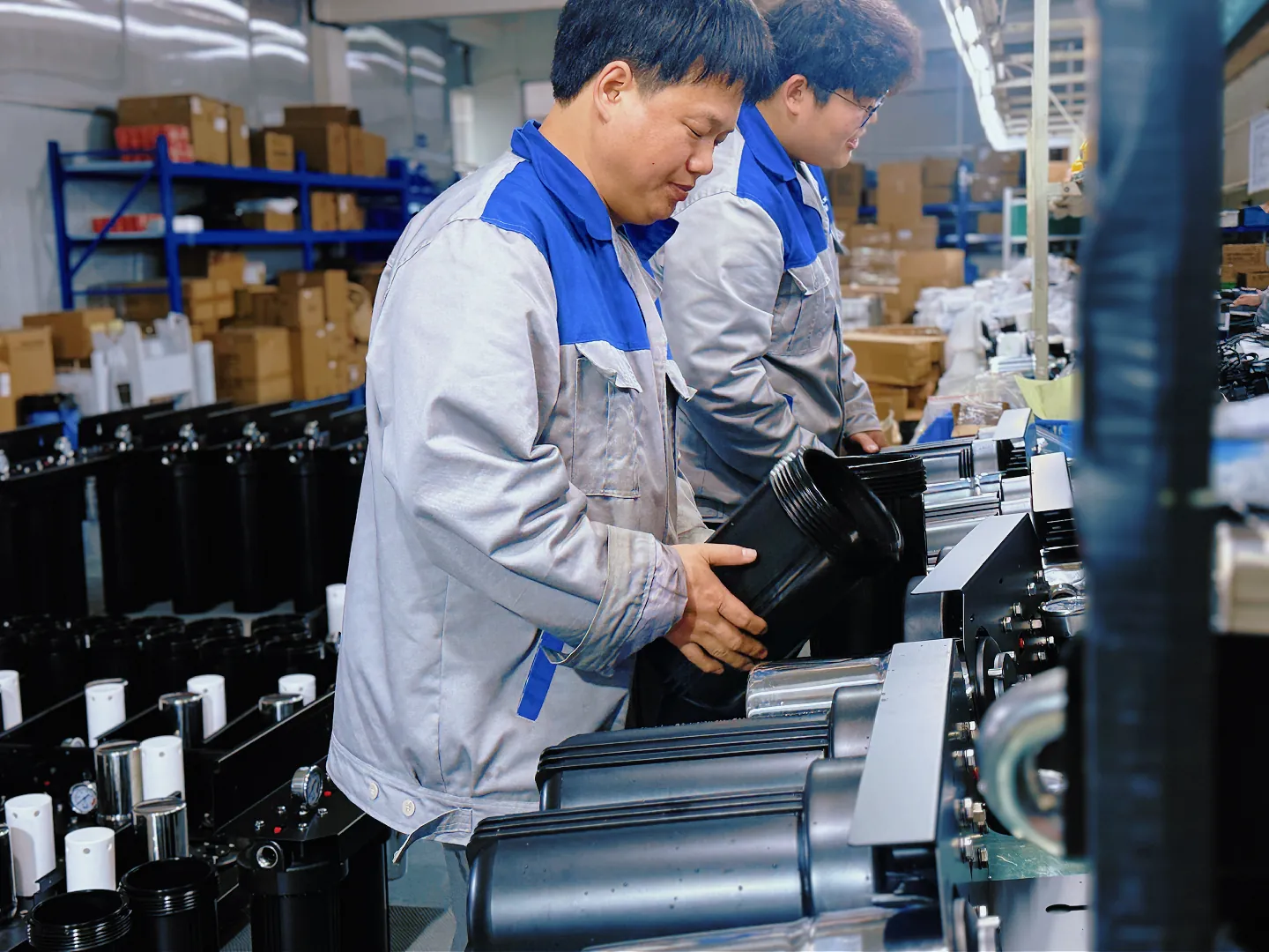
Our OEM and ODM services support private-label products, appliance integration and custom development, including two-week prototype development for suitable projects after confirmation of the engineering scope.
Share your application, peak flow, water analysis or UVT, required outlet criterion, pressure, power supply and available installation space. We will connect the requirement to a product configuration, the relevant test report and a practical verification plan. Contact Agua Topone's engineering team to discuss your UV water treatment project.
Sources and Supporting Documents
- U.S. EPA — UV Disinfection Guidance Manual, Chapter 2: principles, dose and water quality
- CDC — home water treatment and the roles of filtration and UV
- Agua Topone — optical, thermal and manufacturing technology
- SGS NBF25-0016420-01 — AGLED-40002, 4 L/min, report dated August 20, 2025
- SGS NBF25-0011031-01 — AGLED-40012, 50 L/min, report dated June 25, 2025
- Agua Topone — Bulgarian under-sink RO installation
- Agua Topone — U.S. whole-house installation
- Agua Topone — company profile