Contact Us

UVC LED WATER-TREATMENT TECHNOLOGY

UVC LED Technology for UV Water Treatment

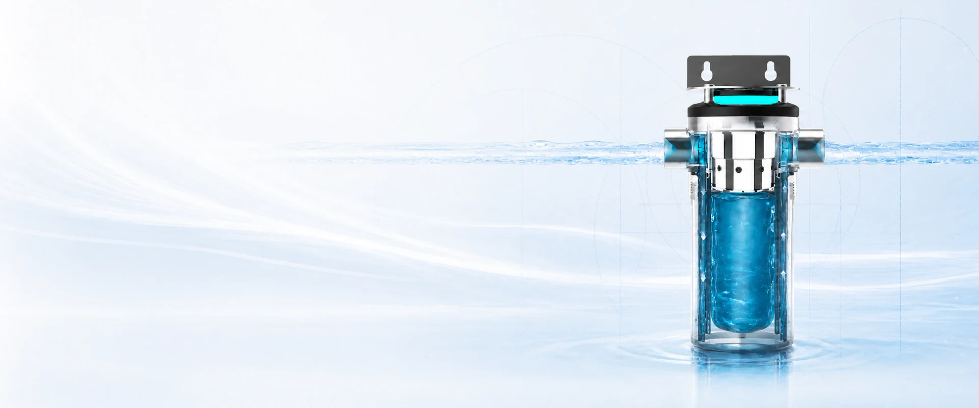
Agua Topone designs UVC LED water-disinfection modules and complete systems around real flow, UVT, water quality and integration requirements—from compact POU equipment to whole-house and OEM applications.

  • On-demand operationInstant switching supports flow-activated control
  • Compact integrationFlexible formats for POU, POE and OEM equipment
  • Mercury-free light sourceSemiconductor UV-C generation without a mercury lamp

HOW UVC LED DISINFECTION WORKS

How UVC LED disinfection works in flowing water

UVC LEDs emit ultraviolet energy into a treatment chamber. As water passes through the irradiation zone, microorganisms absorb UV-C energy in their nucleic acids. This photochemical action can inactivate susceptible microorganisms by preventing normal replication.

Treatment performance depends on more than wavelength. Optical output, exposure time, flow distribution, target organism, UVT, fouling and chamber geometry together determine the UV dose delivered through the reactor.

UV-C treats susceptible microorganisms in the water that passes through the chamber. It does not remove suspended solids, hardness, TDS or dissolved chemicals, and it does not clean an established biofilm from tanks or pipes. Pretreatment, system sanitation and maintenance still have separate roles.

Explore testing and validation

FROM UV-C LIGHT TO WATER TREATMENT

  1. 01
    EmitSelected UV-C wavelengths enter the reactor.
  2. 02
    ExposeFlow and reactor design determine exposure distribution.
  3. 03
    ValidateTesting confirms performance for defined flow and water conditions.
UV dose Intensity × exposure time
This simple relationship explains the principle. Flowing reactors also require hydraulic design, UVT data and product testing to confirm real performance.

DESIGN THE COMPLETE TREATMENT SYSTEM

What determines real UVC LED treatment performance

The LED is one part of the treatment system. Reliable selection starts with the actual water, required flow and installation conditions.

  1. 01

    Treatment target & dose

    Start with the microorganism or treatment objective, then define the UV dose needed for the intended application.

  2. 02

    Flow & hydraulics

    Peak flow, residence time, pressure loss and reactor geometry shape how water moves through the UV-C treatment zone.

  3. 03

    UVT & water conditions

    UV transmittance, turbidity, suspended solids, iron, hardness and fouling affect how UV-C travels through the water.

  4. 04

    Reactor & optical design

    Emitter placement, optical coupling and chamber geometry help distribute UV-C energy through the flowing water.

  5. 05

    Driver, thermal & controls

    Power regulation, heat removal, flow activation, status indication and service access keep the product operating as designed.

Continue with the detailed engineering guides: UVT, flow-rate sizing, WPE and L70 service life.

INSIDE THE SYSTEM

Seven design details behind a reliable UVC LED product

A dependable water-disinfection product comes from coordinating optical, electrical, thermal, mechanical and hydraulic interfaces—not from selecting an LED alone.

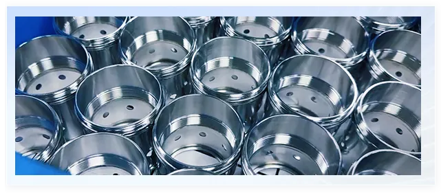
Metal UVC LED component housings illustrating reactor and component geometry

01 TECHNICAL FOCUS

Reactor & Component Geometry

Chamber geometry, material selection, dimensions and component fit are coordinated with the hydraulic path and the intended installation.

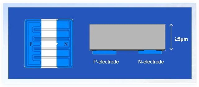
UVC LED electrode detail illustrating the electrical interface

02 TECHNICAL FOCUS

Power & Control Interface

The LED, driver, wiring, status indication and host-equipment signals must work together within the selected product’s rated conditions.

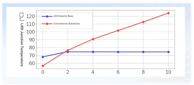
Ceramic UVC LED component base illustrating the thermal path

03 TECHNICAL FOCUS

Thermal Path

The package, mounting surface and heat sink form a continuous path that moves heat away from the LED junction during operation.

UVC LED package surface illustrating heat-dissipation design

04 TECHNICAL FOCUS

Heat Dissipation

Cooling area, mounting, ambient conditions and duty cycle are considered together so the thermal design matches the intended use.

Sealed UVC LED package illustrating moisture-protection design

05 TECHNICAL FOCUS

Sealing & Moisture Protection

Component sealing, electrical protection and reactor seals are coordinated with the product’s installation environment and operating pressure.

UVC LED lens illustrating optical coupling into the reactor

06 TECHNICAL FOCUS

Optical Coupling

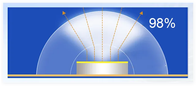
Lens, window, emitter placement and reactor geometry are selected together to direct useful UV-C energy into the treatment zone.

Packaged UVC LED components undergoing identification and quality review

07 TECHNICAL FOCUS

Incoming & Assembly Quality

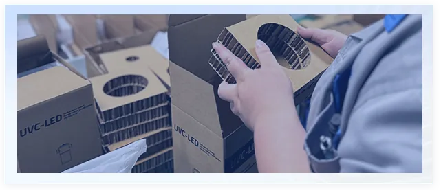
Component identification and incoming inspection support consistent assembly, followed by the applicable functional checks on the finished product.

FROM DESIGN TO FINISHED PRODUCT

How the technology becomes a complete water-treatment system

Application data guides the design. Controlled assembly turns that design into a product, and factory checks confirm the functions required for the approved configuration.

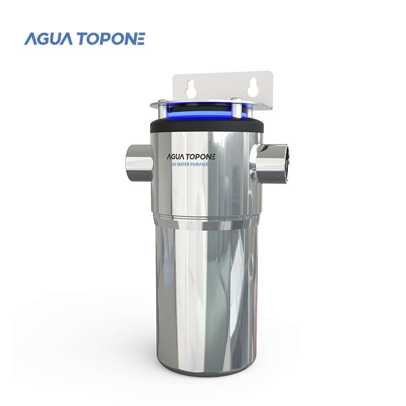
AGLED-40012 UVC LED water-disinfection product platform

DESIGN

Configure the treatment architecture

Application data guides the reactor, LED, driver, controls and mechanical interfaces selected for the product.
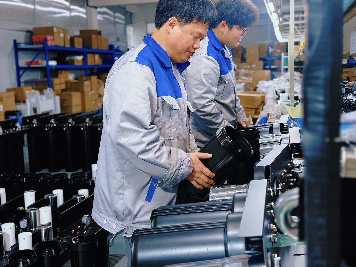
Agua Topone technicians assembling UV water treatment systems

ASSEMBLY

Build the complete water-treatment system

The reactor, driver, controls and treatment components are assembled into the approved product configuration.
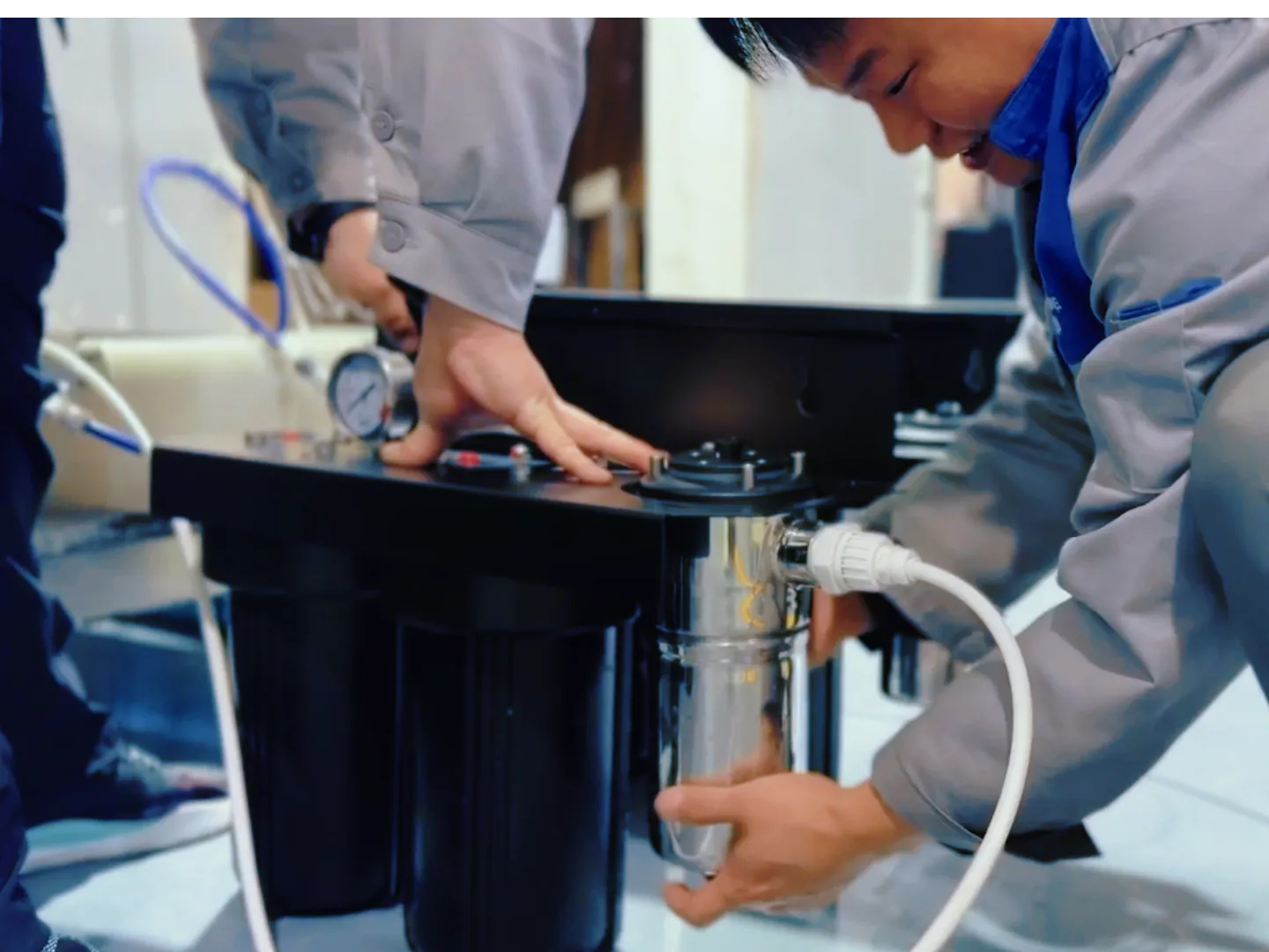
Agua Topone technicians carrying out factory acceptance checks

VERIFICATION

Complete factory acceptance checks

Applicable functional, electrical, leak or pressure and control checks are completed before shipment.

PROJECT ROUTE

A practical path from water data to the right system

Start with a standard product, a configured version or an ODM program. The route depends on flow, water quality, interfaces, market requirements and project volume.

  1. 01

    Share the water and application data

    Confirm application, peak flow, UVT or water analysis, pressure, temperature, installation space and destination market.

  2. 02

    Choose the product route

    Match the project to a compact EC module, stainless-steel AGLED product, complete VPS system or a custom program.

  3. 03

    Confirm system integration

    Coordinate the hydraulic connection, installation space, power, controls, thermal conditions and service access.

  4. 04

    Review performance and documents

    Check the selected model’s flow data, test results, certifications and product documents for the intended use.

  5. 05

    Build and support the approved configuration

    Produce the confirmed configuration and provide the applicable labels, manuals, test files and service information.

Translate the engineering inputs into a product route: POU systems, POE systems or VPS filtration and UVC LED platforms. See the documented production and test videos in Quality & Manufacturing.

ENGINEERING FAQ

Common technology questions

Quick answers on dose, water quality, service life, testing and system integration.

01What dose is required for effective disinfection?

Required dose depends on the target microorganism, UVT, water quality, peak flow and project requirements. Use the selected product's flow data and available validation results for sizing.

02How do UVC LED and conventional UV lamp systems differ?

UVC LED systems use a mercury-free semiconductor light source, support instant switching and can enable compact modular designs. Conventional UV lamp systems remain suitable for many other duties. Choose by validated dose, flow, UVT, certification and service requirements.

03How long does a UVC-LED module last?

Lifetime is model-specific. Current public Agua Topone models commonly use L70 service bases from about 3,000 to 5,000 hours; confirm the exact datasheet and operating conditions before specifying replacement intervals.

04Are test reports available?

Yes. Available documents vary by product and may include optical output, flow data, mechanical checks and microbiological test reports. Public examples include the AGLED-12G SGS report; ask our team for the files relevant to your selected model and market.

05Do I need pre-filtration?

Pre-filtration may be required depending on source-water quality and the selected model's validated operating conditions. Turbidity, suspended solids, iron, manganese, hardness, fouling and low UVT can reduce delivered performance; select pretreatment from water data and the model requirements.

06Can you help with ODM integration?

Yes — AGUA TOPONE offers ODM support, custom module form factors and integration engineering for POU/POE appliance manufacturers.

START WITH THE OPERATING CONDITIONS

Need help matching the technology to your system?

Share the application, peak flow, water quality or UVT, interfaces and target market.

Request an engineering review