
Water dispensers
Low-flow POU treatment where the real draw fits the 2 L/min basis.
COMPACT POU UVC LED MODULE · 0.5 GPM
A lightweight module for dispensers, drinking terminals and OEM integration.
EC-13 combines a 2 L/min flow basis, 2 W input, 55 mW UVC output and a compact 22 × 97 mm envelope for defined POU applications.
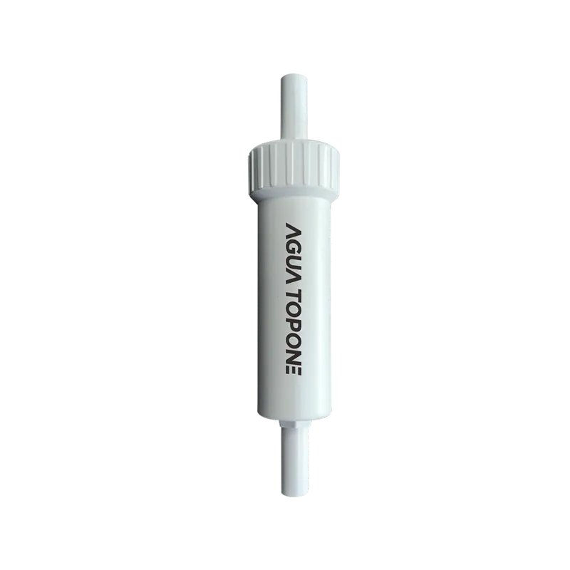
PRODUCT ROLE
EC-13 is intended for dispensers, drinking-water terminals and compact OEM appliances, with a 2 L/min flow basis and a lightweight 22 × 97 mm envelope.
APPLICATION FIT
Low-flow POU treatment where the real draw fits the 2 L/min basis.
Compact terminals using the specified 1/4-inch quick-connect interface.
Lightweight integration with confirmed flow, pressure, mounting and shielding.
Custom water equipment using the correct voltage version, cable and service plan.
ENGINEERING DATA
The current drawing, datasheet and manual are available for project review. Our team will align them with the quoted configuration.
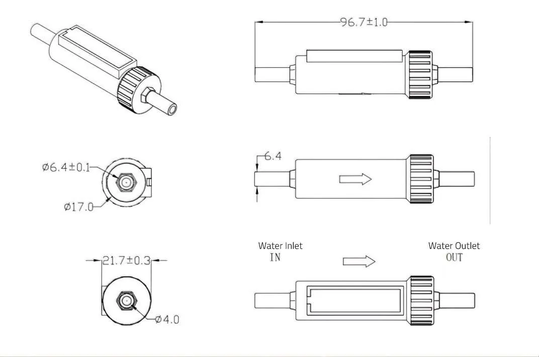
Hydraulic & mechanical
Electrical & optical
| No. | Parameter | Symbol | Value | Unit |
|---|---|---|---|---|
| 01 | Input voltage | VIN | 12 / 24 | V |
| 02 | Input power | W | ≤2 | W |
| 03 | UVC radiation power | Φe | 55 | mW |
| 04 | UVC peak wavelength | WLP | 270–280 | nm |
| 05 | Lifetime test | L70 | ≥5,000 | h |
Product test environment is TC 22°C. Peak-wavelength and radiant-power measurement errors are ±3 nm and ±10%. The 12 V and 24 V entries are different model versions.
OEM INTEGRATION REVIEW
Our application team aligns tube connection, mounting, shielding, pressure, cable routing, voltage version, host controls and technical documents with the appliance design.
Peak flow, UVT, turbidity, temperature and upstream treatment.
Pressure, connection size, flow direction, mounting and service clearance.
Supply voltage, host-appliance logic, flow activation and safe cable routing.
Match the exact model report and compliance documents to the target project.
PRODUCT PERFORMANCE
Current technical specifications, factory-test criteria and applicable series-level compliance documents are available for project review.
Flow, pressure, dimensions, electrical input and optical output are listed for EC-13.
Performance reports and compliance documents are listed independently for straightforward review.
The table below lists the factory test items and acceptance criteria for the specific model.
The table below lists the published factory test items and acceptance criteria for EC-13.
Terminal-to-wire tensile force ≥30 N for 1 minute without loosening; welded wire-to-module tensile force ≥35 N without defects within 10 seconds.
1500 V / 50 Hz AC is applied between the live part and housing for 1 minute; the test sample remains undamaged.
Static pressure is held at 0.4 MPa for 5 minutes without air leakage.
Static water pressure is increased to 0.6 MPa within 5 minutes at a rate of ≤0.4 MPa/s and held for 15 minutes to check module water tightness.
Water pressure is raised to 0.8 MPa within 70 seconds, held for 5 seconds and released; appearance, mechanical and electrical performance remain normal.
10,000 repeated cycles at 0–0.45 MPa with a 2-second pressure rise are used to observe module water tightness.
The water-filled, blocked module is placed at −15°C for 48 hours and then thawed naturally; sealing performance remains normal.
The sample is stored at −15°C ±2°C for 72 hours and recovered at room temperature for at least 1 hour; appearance remains normal, and UVC intensity and module working current meet the drawing requirements.
The sample is stored at 50°C ±2°C for 72 hours and recovered at room temperature for at least 1 hour; appearance remains normal, and UVC intensity and module working current meet the drawing requirements.
The sample cycles 10 times between −15°C ±2°C and 85°C ±2°C with 30-minute holds and a 3-minute conversion time, then recovers at room temperature for at least 1 hour; appearance, UVC intensity and working current meet the drawing requirements.
The module is placed in a 40°C, 85% RH test chamber for 168 hours without damage, and all functions remain available.
The packaged product is tested at 4 Hz (240 CPM) for 60 minutes to ISTA-2001; packaging shows no obvious damage or deformation, the product surface and parts show no mechanical damage, and product function remains normal.
The inner and outer packaging boxes are each allowed to fall freely from 1 metre; packaging shows no obvious damage or deformation, internal fixtures show no obvious displacement, the product and parts show no mechanical damage, and electrical safety, performance and appearance meet the applicable requirements.
Module hazardous-substance content is checked against the limit requirements of the EU RoHS directive.
DOCUMENT CENTER
Drawings, performance reports, installation documents and market files are organized by purpose for easier project review.
APPLICATION REVIEW
Share your peak flow, water quality and integration requirements. Our application team will match the model, configuration and supporting documents to your project.