

How Do You Install a UVC LED Module in a Reverse Osmosis (RO) System?
Direct answer: Install the UVC LED module in series on the final product-water line, after the storage-tank delivery connection and any final post-filter in a tanked system, or after the final post-filter in a tankless system, and immediately before the drinking-water faucet.
This final-stage position helps reduce downstream microbial recontamination while allowing the UVC chamber to receive clear, pretreated water. The module must be installed in series, so every drop sent to the drinking faucet passes through the chamber. Correct placement alone is not enough: the installer must also confirm peak faucet flow, pressure, tubing size, water quality, electrical version and available service space.
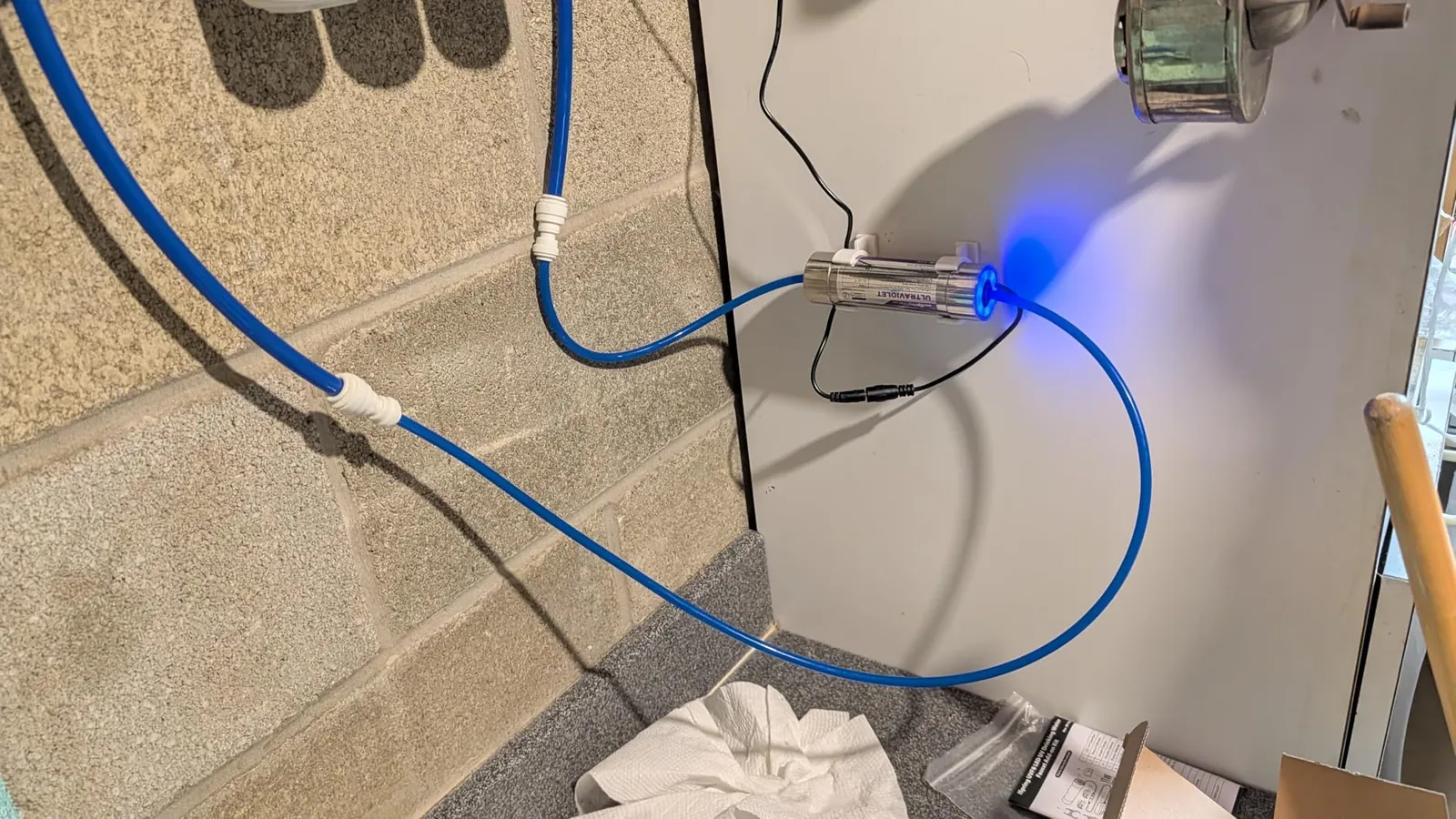
Why Add UVC LED Disinfection After Reverse Osmosis?
Reverse osmosis and UVC perform different jobs. The RO membrane reduces dissolved contaminants and suspended matter, while UVC targets susceptible microorganisms in water passing through the illuminated chamber. An RO system therefore does not automatically eliminate every downstream microbial risk.
After the membrane, purified water may remain inside a storage tank, post-filter, tube or faucet between uses. Maintenance, tubing connections and repeated dispensing can also introduce microorganisms into the final water path. Because RO water normally has no residual disinfectant, the system cannot provide ongoing chemical protection after treatment. A correctly sized UVC LED module adds an on-demand microbial barrier near the point of use without adding chemicals or changing taste.
- Final-stage protection: Water receives UVC exposure shortly before dispensing.
- Instant operation: A flow-activated UVC LED module can start when the faucet opens, without a lamp warm-up period.
- Compact integration: Small modules fit under sinks, inside dispensers and within appliance water paths.
- Clear division of treatment functions: RO handles separation; UVC handles microbial inactivation under the model’s validated flow and water conditions.
However, the UVC chamber treats only the water that passes through it. It does not remove an established biofilm from the storage tank, tubing or faucet. Continue to sanitize the RO system according to the equipment manufacturer’s maintenance procedure.
Where Should the UVC LED Unit Be Installed?
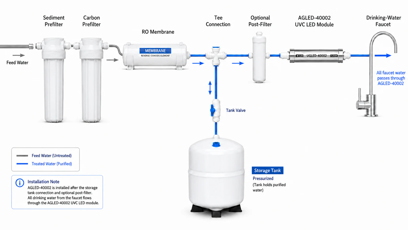
Tanked RO System
RO product water → tank tee / storage-tank delivery → final post-filter → UVC LED → faucet
The storage tank is connected as a branch; this simplified route represents water delivered from the tank toward the faucet.
For a conventional under-sink RO system with a pressurized tank, install the UVC LED module on the tank-delivery line, after the storage-tank connection and any T33 or final post-carbon filter, and before the faucet. This position treats water as it leaves storage and minimizes the amount of tubing located after the UVC chamber. Place the module close enough to the faucet to reduce the downstream water path, while leaving space for inspection and replacement.
Tankless RO System
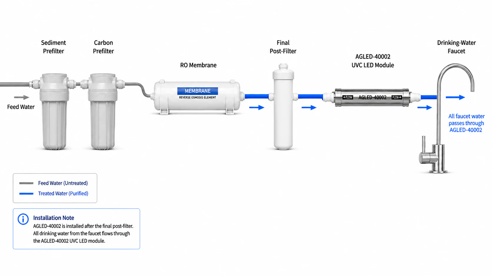
Feed water → prefilters → RO membrane → final post-filter → UVC LED → faucet
Tankless systems produce water on demand, so the UVC LED module usually sits after the final polishing filter or inside the purifier’s final water path. Some appliance designs place the chamber near or inside a specially designed faucet assembly. Regardless of its physical location, all dispensed water must pass through the rated chamber at or below the approved maximum flow.
| Installation position | Best use | Main advantage | Key caution |
|---|---|---|---|
| After the storage-tank delivery connection and final post-filter | Tanked under-sink RO | Treats water after storage and before dispensing | Keep the downstream tube to the faucet as short as practical |
| After the final post-filter | Tankless RO and compact purifiers | Creates a clear final treatment stage | Confirm the instantaneous faucet flow, not only the membrane production rate |
| Near or inside a dedicated faucet assembly | OEM appliance integration | Places treatment close to the outlet | Requires a purpose-designed water path, electrical isolation and service access |
| Inline under the sink | Retrofit installation | Uses the existing final drinking-water tube | Install in series; never create an untreated bypass |
The two configurations are shown separately above because tanked and tankless RO systems use different final treated-water paths. In both layouts, AGLED-40002 remains the last treatment stage before the drinking-water faucet.
Why AGLED-40002 Fits POU RO Integration
The AGLED-40002 (opens in a new tab) is a compact point-of-use UVC LED module designed for under-sink systems, drinking-water dispensers and appliance integration. Its 1/4-inch quick-connect interface matches common RO tubing, while flow-activated operation supports on-demand use at the faucet.
| Maximum design flow | 4 L/min (approximately 1 GPM) |
| Input power | Up to 8 W |
| UVC radiant power | 160 mW |
| UVC peak wavelength | 270–280 nm |
| LED lifetime | L70 ≥5,000 hours |
| Startup flow | >500 mL/min |
| Maximum inlet pressure | 1 MPa |
| Connection | 1/4-inch standard quick-connect |
| Dimensions | Φ38 × 129 mm |
| Net weight | 260 g |
| Electrical versions | 12 V or 24 V versions; confirm the required version before ordering |
When selecting this module, use the RO faucet’s peak dispensing flow. Do not size the UVC unit only from the membrane’s production rate, because a storage tank or booster pump can deliver water at a much higher instantaneous rate than the membrane produces.
What the SGS Test Report Confirms
SGS test report NBF25-0016420-01 (opens in a new tab), dated August 20, 2025, identifies the tested sample as AGLED-40002 at 4 L/min. The challenge test used Escherichia coli ATCC 25922. Influent spiked water contained 2.4 × 10⁶ CFU/100 mL, while the effluent result was below 1 CFU/100 mL. SGS recorded a total-coliform removal rate above 99.999% under those stated conditions.
This result supports a precise, model-specific claim. It should not be presented as proof for every microorganism, every water quality or every flow rate. The AGLED-40002 must remain within its approved hydraulic and water-quality limits to reproduce the intended performance.
For the complete dimensional drawing, connector details and current product configuration, see the AGLED-40002 product information provided above.
The complete SGS report is available through the PDF link above and again in the References section.
Before Installation: Confirm These System Details
- Peak faucet flow: Confirm that dispensing flow does not exceed 4 L/min.
- System type: Identify whether the RO unit uses a storage tank or produces water on demand.
- Tubing: Confirm 1/4-inch tubing and compatible quick-connect components.
- Pressure: Verify that operating and surge pressure remain below the module’s maximum rating.
- Water clarity: Keep sediment and other UV-blocking material upstream. Review UV transmittance in water treatment (opens in a new tab) when water quality is uncertain.
- Electrical version: Select the correct 12 V or 24 V version and matching power supply.
- Mounting space: Leave room for tubing bends, connector release and future service.
- Drain protection: Consider a drip tray or leak sensor in cabinets where a leak could damage furniture.
How to Install a UVC LED in an RO System: Step by Step
1. Shut Off and Depressurize the RO System
Close the feed-water valve and storage-tank valve, then open the drinking faucet to release pressure. Disconnect electrical power from pumps and accessories before working inside the cabinet. Prepare a clean tubing cutter, suitable brackets, towels and the correct quick-connect parts.
2. Identify the Final Treated-Water Line
Trace the tube that carries finished water to the faucet. On a tanked system, select the line after the storage-tank delivery connection and final polishing filter. On a tankless system, select the line after the last treatment cartridge. Do not connect the module to the raw-water feed or create a branch that lets untreated water reach the same faucet.
3. Choose and Mark the Mounting Position
Position the module close to the faucet while keeping electrical connectors dry and accessible. Avoid sharp tube bends, heat sources and locations where stored items could strike the unit. Mark the bracket location and confirm that the tube can reach both ports without tension.
4. Cut and Connect the Tubing
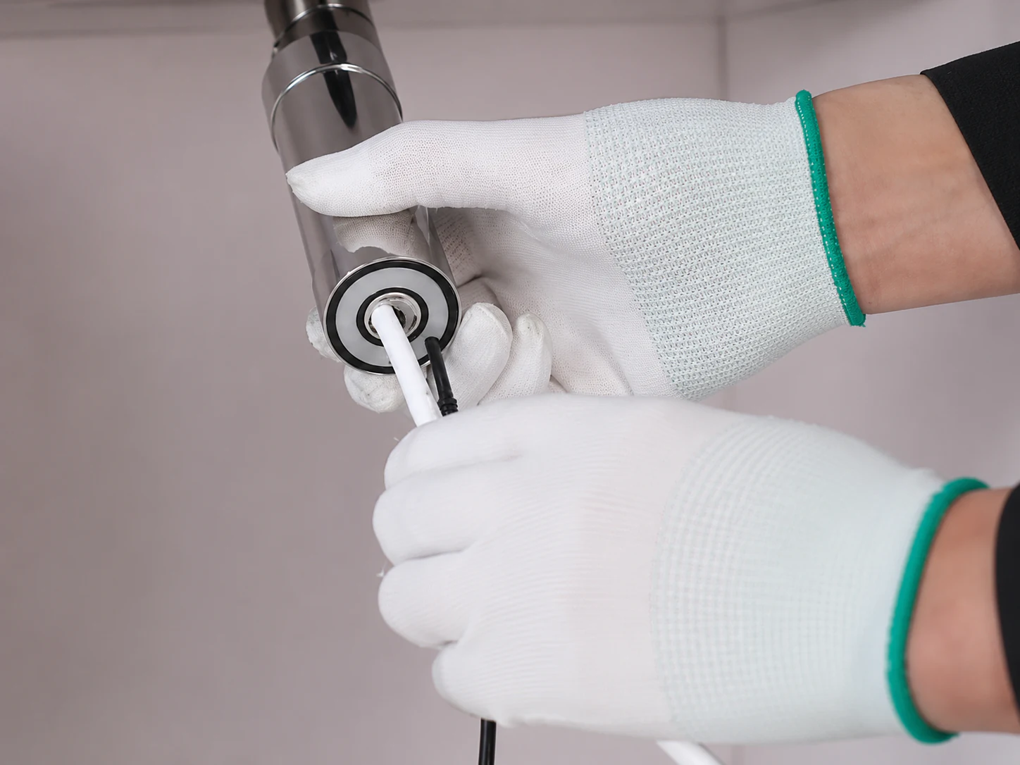
Cut the 1/4-inch tube squarely with a tubing cutter. Follow the inlet and outlet marks on the AGLED-40002, then push each tube fully into the quick-connect port. Pull back gently to confirm engagement. Do not apply thread-seal tape to push-fit connections; use it only on a compatible threaded adapter when the adapter manufacturer requires it.
5. Secure the Module
Fix the chamber to a stable cabinet wall or equipment frame with the specified bracket. Do not let flexible tubing carry the module’s weight. Maintain enough clearance to release the quick-connect collets and remove the unit during service.
6. Connect the Correct Power and Control
Connect the selected 12 V or 24 V version only to its specified power supply and controller. Keep the power supply, plug and non-waterproof connectors away from leaks and condensation. Follow local electrical requirements for outlets used near plumbing.
7. Flush, Leak-Test and Commission the System
Open the valves slowly and inspect every connection before applying full pressure. Run the faucet to remove trapped air and flush the final line. Confirm that the UVC LED activates when flow exceeds the startup threshold and stops when flow ends. Check the faucet flow against the 4 L/min maximum, then inspect the fittings again after several on/off cycles.
Flow Switch and Flow Restrictor Are Not the Same
The AGLED-40002 uses flow-activated control to turn the UVC LEDs on when water moves through the chamber. This control reduces unnecessary operating time, but it does not automatically prevent the RO system from exceeding 4 L/min.
A flow switch or sensor detects water movement and controls electrical operation. A flow restrictor changes the hydraulic flow. Add or adjust a restrictor only when measured peak faucet flow exceeds the module rating and the RO equipment design allows that change. Incorrect restriction can reduce faucet performance or affect a tankless RO system’s pump logic. See our guide on how flow rate affects UVC LED disinfection (opens in a new tab).
Safety and Maintenance
- Never look directly at an operating UVC source or open the sealed chamber while powered.
- Keep the controller, power supply and connectors dry.
- Inspect tubing and quick-connect fittings for movement, stress or leakage.
- Replace upstream RO filters on schedule to protect water clarity and system flow.
- Sanitize the storage tank, faucet and final tubing according to the RO manufacturer’s instructions.
- Track operating hours and replace the UVC LED module at the specified service interval.
- Recheck flow after changing filters, pumps, tanks, faucets or restrictors.
Common Installation Mistakes to Avoid
- Installing before the RO membrane: This exposes the UVC module to poorer water quality and leaves downstream components unprotected.
- Installing before the storage tank: Water can still remain in the tank and final tube after UVC treatment.
- Creating a T-fitting bypass: Some faucet water may avoid the UVC chamber.
- Sizing from membrane production only: The faucet can discharge faster than the membrane produces water.
- Confusing flow activation with flow control: The LED may switch on correctly even when hydraulic flow is too high.
- Leaving long downstream tubing: This increases the water path after treatment.
- Skipping sanitation: A UVC chamber does not clean established biofilm from system surfaces.
Frequently Asked Questions
Should the UVC LED Be Installed Before or After the RO Storage Tank?
Install it on the tank-delivery line, after the storage-tank connection and any final post-filter, and before the faucet. This allows water leaving storage to receive final UVC treatment shortly before dispensing.
Can AGLED-40002 Be Used in a Tankless RO System?
Yes, when the final water path, peak flow, pressure, tubing and electrical interface match the module’s specifications. Install it after the RO membrane and final post-filter.
Does the Built-In Flow Control Limit Water to 4 L/min?
No. Flow activation controls when the LEDs operate. The installer must measure or verify peak hydraulic flow separately and add an appropriate restriction only when the RO design requires it.
Does UVC Remove Biofilm from the RO Tank?
No. UVC inactivates susceptible microorganisms in water passing through the chamber. It does not remove attached biofilm, so routine system sanitation remains necessary.
Conclusion
The best location for a POU UVC LED module is the final product-water line before the faucet. In a tanked RO system, place AGLED-40002 after the storage-tank delivery connection and any final post-filter. In a tankless system, place it after the final post-filter. Install the module in series, keep peak flow at or below 4 L/min, use the correct electrical version and complete a careful leak and activation test.
For brands developing a new purifier rather than retrofitting an existing system, Agua Topone can review the water path, flow, pressure, connector, control interface and target-market documentation through our OEM/ODM UVC LED integration service (opens in a new tab). You can also review the existing AGLED-40002 under-sink application case (opens in a new tab) and our broader POU UVC LED solutions (opens in a new tab).
References
- SGS-CSTC Standards Technical Services Co., Ltd., Ningbo Branch. Test Report NBF25-0016420-01 (opens in a new tab), August 20, 2025.
- Atlantic Ultraviolet Corporation. How to Install Your Point of Use UV Water Purifier (opens in a new tab), June 10, 2026.