How Does Flow Rate Validation Influence UVC LED Water Sterilizer Performance? A Technical Analysis of GPM vs. LPM Standards
The evolution of water treatment technologies has reached a critical juncture with the emergence of ultraviolet-C (UVC) Light Emitting Diodes (LEDs). As industrial, commercial, and residential sectors shift toward sustainable and chemical-free disinfection, the technical parameters governing these systems require rigorous standardization. Among these, the volumetric flow rate—commonly expressed in Gallons Per Minute (GPM) or Liters Per Minute (LPM)—serves as the primary determinant of germicidal efficacy. The precise determination of flow rate standards through biodosimetry and Computational Fluid Dynamics (CFD) modeling ensures that UVC LED reactors deliver a consistent germicidal dose, effectively inactivating 99.999% of pathogens while maintaining energy efficiency.
Why Does Water Flow Rate Matter in UVC LED Sterilizers?
The fundamental objective of a UVC LED water sterilizer is the delivery of a lethal ultraviolet dose to microorganisms as they pass through a treatment chamber. This process relies on the intersection of optical physics and fluid mechanics. Unlike traditional systems, UVC LEDs allow for compact, modular designs that require a sophisticated understanding of how water moves relative to the light source.
What is UV Dose (RED) and How is it Calculated?
The industry defines the “UV Dose,” or fluence, as the total radiant energy received by a specific surface area. The governing equation for this process is:
$$D = I \times T$$
In this equation, $D$ represents the UV Dose in millijoules per square centimeter ($mJ/cm^2$), $I$ denotes the UV Intensity or irradiance in milliwatts per square centimeter ($mW/cm^2$), and $T$ signifies the exposure or residence time in seconds. In a dynamic flow environment, the residence time ($T$) is inversely proportional to the flow rate ($Q$). As the flow rate increases, the time that a microorganism spends in the irradiation zone decreases, potentially compromising the sterilization outcome if the intensity is not sufficiently high.
Engineers must also account for the Ultraviolet Transmittance (UVT (opens in a new tab)) of the water, which measures the percentage of light that penetrates through a 1 cm path. The relationship between dose and UVT is expressed through a modified version of the Beer-Lambert Law:
$$D = \left( \frac{I_0 \cdot (1 – 10^{-A \cdot L})}{A \cdot \ln(10)} \right) \times T$$
Where $I_0$ is the initial intensity, $A$ is the absorbance (related to UVT), and $L$ is the path length. For professional systems such as the AguaTopone VPS series (opens in a new tab), designs typically assume a baseline UVT of 90% to ensure reliability across varying water qualities.
The Role of Residence Time Distribution (RTD)
A common misconception in water treatment is that water moves as a uniform “plug” through the reactor. In reality, different parcels of water travel at different velocities due to friction near the chamber walls and turbulence in the center. This phenomenon, known as Residence Time Distribution (RTD), means that some microorganisms may exit the reactor faster than others, receiving a “sub-lethal” dose.
Table 1: Impact of Flow Rate on Theoretical Residence Time and UV Dose
| Flow Rate (GPM) | Flow Rate (LPM) | Residence Time (s) | UV Intensity (mW/cm2) | Delivered Dose (mJ/cm2) |
| 0.5 | 1.89 | 10.0 | 5.0 | 50.0 |
| 1.0 | 3.79 | 5.0 | 5.0 | 25.0 |
| 2.0 | 7.57 | 2.5 | 5.0 | 12.5 |
| 5.0 | 18.93 | 1.0 | 5.0 | 5.0 |
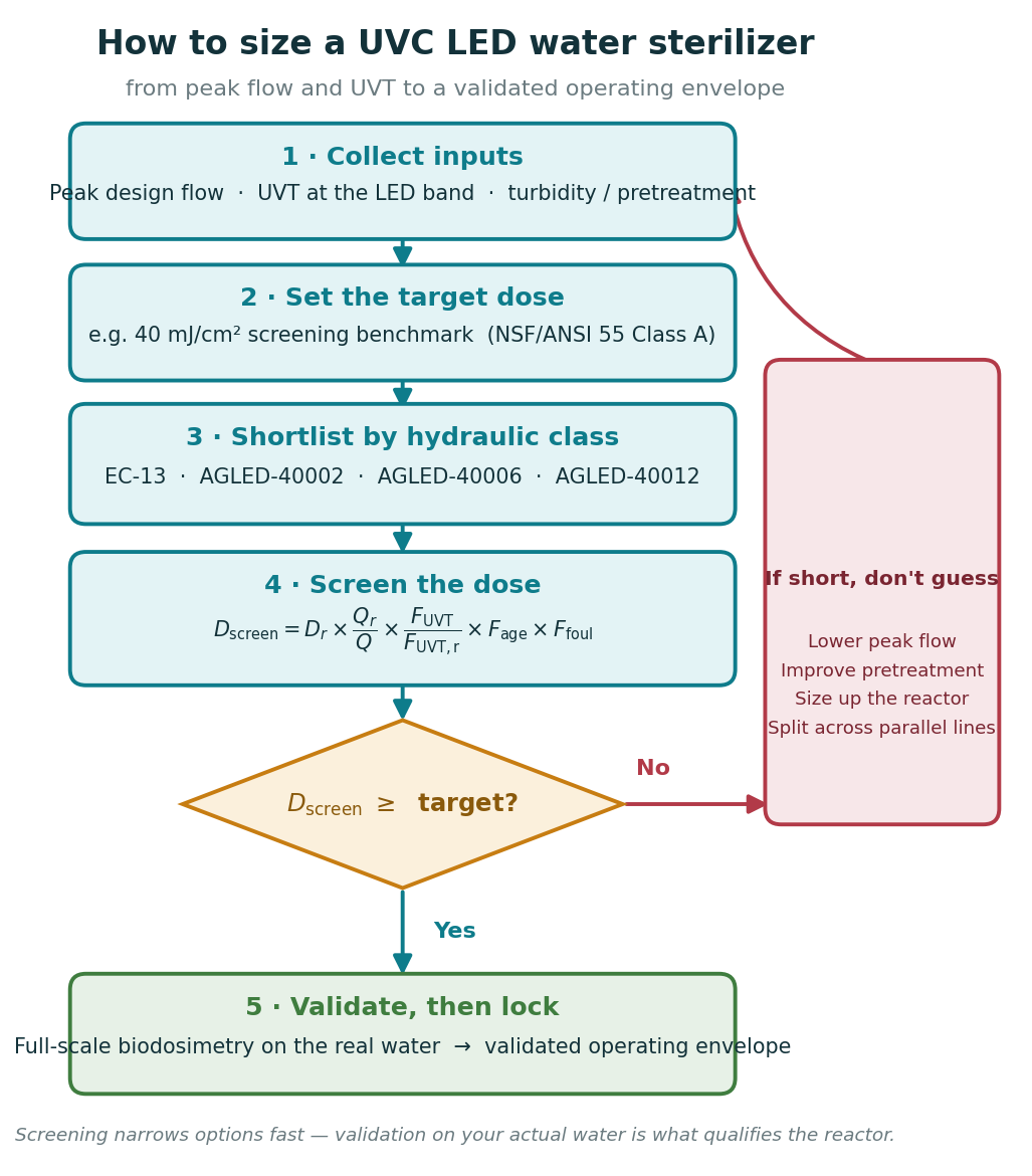
The data in Table 1 illustrates the critical need for precise flow control. To maintain a target dose of $40$ $mJ/cm^2$—the standard for Class A UV systems—manufacturers must either restrict the flow rate or increase the number of LED chips in the array to raise the intensity.
How is UVC LED Sterilizer Performance Validated?
To establish a “rated flow” for a UVC LED system, manufacturers do not rely solely on theoretical calculations. Instead, they employ two primary validation pillars: Biodosimetry and Computational Fluid Dynamics (CFD).
Biodosimetry: Biological Performance Verification
Biodosimetry is the “gold standard” for UV reactor validation. It involves the use of non-pathogenic surrogate microorganisms to measure the “Reduction Equivalent Dose” (RED) of a system. This method provides empirical proof of a system’s ability to inactivate specific pathogens like E. coli, Cryptosporidium, or Giardia.
The validation process follows a rigorous sequence:
- Preparation of the Surrogate: Lab technicians culture a specific batch of surrogates, such as the MS2 bacteriophage or Bacillus subtilis spores. Each batch’s sensitivity to UVC is verified using a collimated beam apparatus to create a dose-response curve.
- Reactor Challenge: The surrogates are injected into the influent of the UVC LED reactor at controlled flow rates (e.g., 1 GPM, 5 GPM, 10 GPM).
- Sampling and Analysis: Effluent samples are collected and analyzed for log reduction. If a 4-log reduction (99.999%) is observed for a surrogate with a known sensitivity of $30$ $mJ/cm^2$, the reactor is credited with delivering that RED at that specific flow rate.
- Factor of Safety: Engineers apply a “Validation Factor” to the results to account for uncertainties in flow measurement and LED aging, ensuring the system performs reliably throughout its lifecycle.
CFD Modeling: The Virtual Fluid Laboratory
Computational Fluid Dynamics (CFD) serves as a powerful design and optimization tool that complements biodosimetry. By creating a 3D digital twin of the disinfection chamber, engineers can visualize and analyze the complex interactions between fluid flow and the UVC radiation field.
CFD modeling typically utilizes the following mathematical frameworks:
- The Navier-Stokes Equations: These fundamental equations describe the motion of fluid substances. In UVC reactors, they help identify regions of high and low velocity.
- The $\kappa-\epsilon$ Turbulence Model: This model calculates the turbulent kinetic energy ($\kappa$) and the dissipation rate ($\epsilon$), allowing engineers to design reactors that promote mixing and prevent “dead zones”.
- Lagrangian Particle Tracking: The software simulates thousands of individual particles (representing microbes) moving through the reactor. For each particle, the software calculates the cumulative UV intensity it encounters along its specific path.
- The Discrete Ordinates (DO) Radiation Model: This model simulates the UVC light’s path, accounting for reflections off the 304 or 316 stainless steel reactor walls and absorption by the water.
Table 2: Comparison of Lagrangian and Eulerian CFD Modeling Methods
| Metric | Lagrangian Method | Eulerian Method |
| Primary Focus | Tracking individual particles | Calculating concentrations in volume cells |
| Data Output | Particle-specific UV dose | Spatial distribution of inactivation |
| Complexity | High (Requires many trajectories) | Moderate |
| Ideal Use Case | Precision dose distribution analysis | General reactor performance trends |
The use of CFD allows brands like AguaTopone to optimize the geometry of their chambers—such as implementing tangential inlets—before physical prototypes are even built. Optimized swirl-flow designs can improve disinfection efficiency by over 30% by ensuring a more uniform residence time distribution.
Global Flow Standards and Regional Unit Preferences
The selection of a UVC LED water sterilizer often depends on regional plumbing standards and the units used to measure volume and time. Understanding these differences is essential for international procurement and system integration.
North America: The GPM Standard
In the United States and Canada, the Gallon Per Minute (GPM) is the dominant unit for residential, commercial, and industrial water applications. This preference is rooted in the US Customary System and is supported by regulatory bodies like the EPA and organizations such as the National Sanitation Foundation (NSF).
- Residential Focus: Most under-sink Point-of-Use (POU) systems are rated between 0.5 and 1.5 GPM, while Whole-House Point-of-Entry (POE) systems range from 8 to 20 GPM.
- Measurement Basis: One US Gallon is defined as exactly 231 cubic inches or approximately 3.785 liters.
Europe and Asia: The Shift to LPM and $m^3/h$
Most of the world outside of North America utilizes the metric system. Liters Per Minute (LPM) is the standard for smaller consumer appliances, while Cubic Meters Per Hour ($m^3/h$) is preferred for industrial and municipal water treatment plants.
- LPM Usage: Used extensively in the European Union, China, and Southeast Asia for water dispensers, ice makers, and dental equipment.
- $m^3/h$ Usage: This unit is essential for high-flow industrial workflows, where 1 $m^3/h$ is equivalent to 1,000 liters per hour.
The Imperial vs. US Gallon Distinction
A critical area of potential error involves the historical difference between the US Gallon and the British Imperial Gallon. The Imperial Gallon is approximately 1.2 times (20%) larger than the US Gallon.
- 1 US Gallon $\approx$ 3.785 Liters.
- 1 Imperial Gallon $\approx$ 4.546 Liters.
If a professional assumes “GPM” refers to Imperial gallons in a US-manufactured system, the actual flow rate will be 20% higher than intended, leading to a corresponding 20% drop in UV dose. This distinction is vital for projects in the UK, Australia, and parts of the Caribbean.
Table 3: Regional Flow Unit Summary by Sector
| Region | Household (POU) | Whole Facility (POE) | Industrial |
| USA / Canada | GPM | GPM / GPH | GPM / MGD |
| UK / Commonwealth | LPM / Imp. GPM | LPH / Imp. GPM | $m^3/h$ |
| European Union | LPM | LPH | $m^3/h$ |
| Asia (China/Japan) | LPM | LPM / LPH | $m^3/h$ |
How to Choose Between POU and POE UVC LED Systems?
For global engineers, the ability to convert flow rates with high precision is non-negotiable. These conversions allow for the accurate scaling of UVC LED power levels to meet the requirements of different markets.
Mathematical Conversion Factors
The following constants form the basis of all flow rate transformations:
- To convert GPM (US) to LPM: Multiply by 3.78541.
- To convert LPM to GPM (US): Multiply by 0.264172.
- To convert $m^3/h$ to LPM: Multiply by 16.6667.
- To convert $m^3/h$ to GPM (US): Multiply by 4.40288.
Applied Engineering Examples
Consider a hydraulic system design for an industrial application requiring a flow rate of 15 GPM. To select a metric-rated pump, the engineer performs the following calculation:
$$15 \text{ GPM} \times 3.78541 = 56.78 \text{ LPM}$$
To convert this further into an hourly metric for industrial reporting:
$$56.78 \text{ LPM} \times 0.06 = 3.41 \text{ } m^3/h$$
This multi-step conversion ensures that components selected from European or Asian manufacturers (who rate in LPM or $m^3/h$) are perfectly sized for the North American requirement.
Table 4: High-Precision Flow Conversion Matrix
| Source Unit | Target: GPM (US) | Target: LPM | Target: LPH | Target: m3/h |
| 1 GPM (US) | 1.000 | 3.785 | 227.1 | 0.227 |
| 1 LPM | 0.264 | 1.000 | 60.00 | 0.060 |
| 1 LPH | 0.004 | 0.016 | 1.000 | 0.001 |
| 1 $m^3/h$ | 4.403 | 16.66 | 1000 | 1.000 |
Material Safety: The Significance of NSF 372 Lead-Free Certification
Beyond the biological efficacy of the UVC light, the safety of a water treatment system depends on the materials that come into contact with the fluid. AguaTopone holds the NSF/ANSI 372 (opens in a new tab) (Lead-Free) certification, ensuring that its UVC LED modules do not introduce heavy metal contaminants into the drinking water stream.
Understanding the Lead-Free Requirement
The NSF/ANSI 372 standard was established to verify that the materials and components in a drinking water system meet the federal “low-lead” requirement of the United States Safe Drinking Water Act.
- The Weighted Average Rule: A product is considered lead-free if the weighted average lead content of its wetted surfaces is $\leq 0.25\%$.
- Solder and Flux: For solders and fluxes, the lead content must be $\leq 0.2\%$.
- Verification: Certification involves a physical audit of the manufacturing facility and a detailed chemical analysis of all alloys and components used in the reactor.
Impact on Product Selection
For schools, hospitals, and office buildings in older urban centers, selecting NSF 372-certified hardware is a regulatory and health priority. While a carbon filter may remove lead from the incoming water, the UVC LED reactor itself must not become a source of secondary contamination. AguaTopone’s use of 304 stainless steel and lead-free inlets/outlets in the VPS series provides a dual-layer of protection: biological inactivation and chemical purity.
Professional Selection Guide: AguaTopone POU vs. POE Modules
Selecting the correct flow rate is the most critical step in system design. Professionals must match the “Peak Demand” of the application with the “Validated Flow Rate” of the UVC LED module.
Point-of-Use (POU) Modules: Terminal Disinfection
POU systems are designed for installation at the exact point where the user accesses the water. These modules are characterized by compact sizes and “instant-on” capabilities.
- AguaTopone EC-11 (1 LPM / 0.4 GPM): Optimized for low-flow environments such as coffee machines, dental chairs, and medical dispensers.
- AguaTopone EC-12 (4 LPM / 1 GPM) (opens in a new tab): The professional standard for residential kitchen faucets and office water coolers. This module features an integrated flow switch that ensures the LED array only activates when water is moving, significantly extending its 5,000-hour lifespan.
- AguaTopone EC-13 (2 LPM / 0.5 GPM): An array-type high-intensity module designed for industrial OEM integration (opens in a new tab) where space is limited but high dosage is required.
Point-of-Entry (POE) Systems: Whole-Facility Sterilization
POE systems are installed where the main water line enters the facility. These systems require high power and robust fluid dynamics to handle multiple simultaneous users.
- VPS-103 / VPS-104 (30 LPM / 8 GPM): Suitable for small to medium-sized residential homes or small commercial offices. These systems integrate sediment and carbon filtration stages before the UVC LED chamber.
- VPS-203 / VPS-204 (45 LPM / 12 GPM): The flagship POE solution for large facilities, providing 99.999% pathogen destruction at high flow rates.
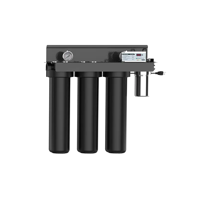
Table 5: Technical Specifications of AguaTopone UVC LED Range
| Model | Flow Rate (LPM) | Flow Rate (GPM) | Power (W) | LED Lifespan (h) | Connection |
| EC-11 | 1.0 | 0.4 | 1.8 | 4,000 | 1/4″ Quick |
| EC-13 | 2.0 | 0.5 | 2.0 | 5,000 | 1/4″ Quick |
| EC-12 | 4.0 | 1.0 | 4.8 | 5,000 | 1/4″ or 3/8″ |
| VPS-103 | 30.0 | 8.0 | 50.0 | 5,000 | 1″ Female |
| VPS-204 | 45.0 | 12.0 | 50.0 | 5,000 | 1″ Female |
How Durable Are UVC LED Modules in Real-World Plumbing?
A professional-grade UVC LED system must do more than kill bacteria; it must survive the harsh realities of plumbing environments. AguaTopone validates its modules through a comprehensive suite of mechanical and electrical stress tests conducted in ISO 17025 accredited laboratories.
Pressure and Sealing Integrity
- Static Pressure Test: Modules must maintain 0.4 MPa (58 PSI) for 5 minutes without any air leakage. 1
- Burst and Resistance Test: The housing is subjected to 1.2 MPa (174 PSI) for 15 minutes. This ensures the 304 stainless steel and quartz sleeves do not fail during sudden water hammer events.
- Cyclic Pressure Test: To simulate years of usage, the module is cycled 10,000 times between 0 and 1.04 MPa. This test identifies potential fatigue in the seals and quick-connect fittings.
Environmental and Lifespan Verification
- The L70 Standard: AguaTopone adheres to the L70 metric, ensuring that the UVC LED output does not drop below 70% of its initial radiant power within its rated lifespan (typically 5,000 hours of active operation).
- Thermal Shock and Freezing: Modules are filled with water and frozen at $-18^\circ C$ for 48 hours, then cycled through temperatures as high as $+85^\circ C$. This ensures the system remains robust in various climates, from northern winters to tropical summers.
- Dry Burning Test: Unlike mercury lamps, UVC LEDs can be operated in a waterless state. AguaTopone modules are tested for 24 hours of dry operation to ensure the heat dissipation system protects the circuitry even if the water supply is cut off.
Conclusion: Strategic Procurement of UVC LED Systems
The transition from conventional disinfection to UVC LED technology requires a shift in how professionals evaluate performance. The “rated flow” of a system is not an arbitrary number; it is a scientifically determined boundary established through biodosimetry and CFD modeling. By prioritizing validated flow rates in GPM or LPM and selecting NSF 372-certified materials, project managers can ensure that their water treatment infrastructure is biologically effective, chemically safe, and globally compliant.
AguaTopone’s 20-year legacy in water treatment (opens in a new tab), combined with its rigorous SGS-verified testing protocols, positions its EC and VPS series as the industry benchmark for reliable UVC LED disinfection. Whether for a single medical dispenser or a whole-facility industrial workflow, the synergy of optical precision and fluid dynamic optimization ensures that every drop of water is safe for consumption.
Frequently Asked Questions (FAQs) About Flow Rate and UV Disinfection
Q1: Does a higher flow rate mean lower disinfection efficiency? Yes. If the water flows through the UVC LED chamber too quickly, the pathogens are exposed to the UV light for a shorter time. This reduces the UV Dose (RED), meaning fewer bacteria and viruses are deactivated. Always ensure your flow rate does not exceed the system’s maximum capacity.
Q2: How do I know the flow rate of my home or commercial water supply? You can easily test this by placing a 1-gallon (or 1-liter) bucket under your faucet or pipe and timing how many seconds it takes to fill. Divide 60 by that number of seconds to get your Gallons Per Minute (GPM) or Liters Per Minute (LPM).
Q3: What happens if my water flow exceeds the UVC LED sterilizer’s maximum rating? The water will not receive the required 40 mJ/cm² (or minimum standard) UV dose. This results in under-treated water, leaving live pathogens in your drinking supply. If you experience peak flows higher than your current system, you should upgrade to a larger Point-of-Entry (POE) system like the AGLED 40012.
Q4: Do UVC LED sterilizers restrict water pressure? High-quality UVC LED water sterilizers, like those engineered by Agua Topone, are designed with optimized reactor chambers that cause minimal to no noticeable drop in water pressure, provided they are sized correctly for your main line.