

What Is the Difference Between UV Water Disinfection and Water Filtration?
Water filtration removes particles and selected dissolved contaminants from water, while UV water disinfection inactivates microorganisms by damaging their DNA or RNA. Filtration handles removal; UV handles microbial inactivation. When a water supply needs both functions, a combined system uses filtration first and UV disinfection afterward.
A sediment filter can catch visible rust without stopping every microorganism. Equally, a UV reactor can inactivate microbes without removing rust, chlorine, or dissolved salts. The useful question, therefore, is what each stage contributes—and how the two work together.
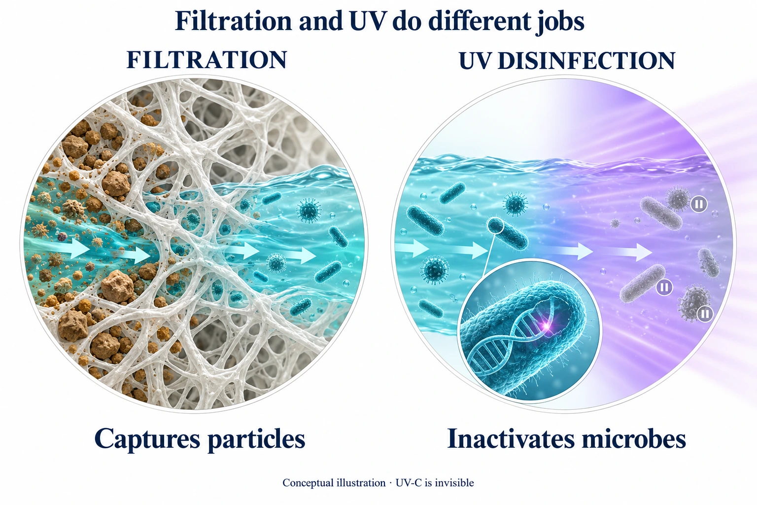
UV Disinfection vs. Filtration: The Core Differences
| Treatment question | Water filtration | UV water disinfection |
|---|---|---|
| What does it do? | Captures particles, adsorbs contaminants, or separates substances through a membrane | Exposes microorganisms to germicidal ultraviolet light |
| What happens to microorganisms? | Suitable microbial filters retain them; ordinary sediment and carbon cartridges do not provide the same protection | UV damages genetic material and prevents replication |
| Does it remove sediment? | Yes, with appropriate sediment filtration | No |
| Does it address chlorine, taste, and odor? | Suitable activated-carbon cartridges do | UV does not remove these substances |
| Does it reduce dissolved salts? | Reverse osmosis does; ordinary sediment and carbon cartridges do not | No; dissolved minerals remain in the water |
| What requires maintenance? | Filter media accumulate contaminants and need replacement or cleaning | The light source, optical surfaces, controls, and reactor require scheduled service |
This division explains why equipment often combines both processes under the familiar name “UV water filter.” Inside that equipment, the filter and the UV reactor still perform different jobs. [1][2]
How Does Water Filtration Work?
Filtration uses a physical barrier, an adsorbent surface, or a membrane to separate unwanted substances from water. Three common stages illustrate the difference.
Sediment filtration catches suspended solids. Polypropylene (PP) cartridges trap sand, silt, rust, and other particles as water moves through their fibers or pores. As a result, they improve clarity and protect downstream components from particulate fouling.
Activated carbon adsorbs contaminants onto its internal surfaces. Granular activated carbon (GAC) and carbon block (CTO) cartridges commonly address chlorine, taste, and odor. Specialized carbon media also target contaminants such as particular organic chemicals, chloramines, or lead; the cartridge's performance specification identifies its actual reduction capability. NSF/ANSI 42 covers aesthetic claims, while NSF/ANSI 53 covers specified contaminants with health effects. [2]
Reverse osmosis separates dissolved substances through a membrane. An RO system uses pressure to move water through a semi-permeable membrane and reduce dissolved salts and other specified contaminants. This process differs from sediment filtration, which does not remove dissolved ions simply by making its cartridge finer. [1][2]
Why clearer water does not automatically mean disinfected water
A filter's appearance and micron label do not establish every treatment capability. Some membranes and microbial filters provide defined organism-removal performance. However, an ordinary taste-and-odor cartridge does not become a disinfectant merely because the water looks clean.
Furthermore, damp cartridges, storage tanks, and downstream tubing can support microbial growth. Consequently, designers consider both the filter's removal capability and the need for a dedicated disinfection stage.
How Does UVC LED Water Disinfection Work?
UV disinfection uses light rather than a trapping medium. As water flows through the reactor, microorganisms absorb UV-C energy. That energy damages their genetic material and disrupts replication, so the reactor inactivates them instead of collecting them in a cartridge. The U.S. EPA explains this photochemical mechanism in its UV Disinfection Guidance Manual. [3]
UV treatment leaves TDS, pH, mineral hardness, and dissolved oxygen unchanged. It also does not perform the jobs of a softener, carbon cartridge, or RO membrane. Instead, it adds a microbial-treatment stage without dosing a chemical disinfectant into the water or changing its taste.
From semiconductor chip to germicidal light
Inside an aluminum gallium nitride (AlGaN) UVC LED, electrons and holes recombine in thin semiconductor layers called quantum wells. This process generates ultraviolet photons. Agua Topone's published UVC LED models operate in the 270–280 nm band. [4][5]
Microbial nucleic acids absorb germicidal UV energy. Photochemical lesions, including pyrimidine dimers, interfere with DNA or RNA function and prevent normal replication. In a flowing system, the treatment outcome depends on the energy each microorganism receives during its passage through the irradiation zone. [3]
Why packaging and reactor construction matter
Generating UV-C is only the first step. The finished system must transfer light into the water, remove heat from the LED, and maintain a dependable water path. Agua Topone's published engineering details show how these functions connect: [4]
- AlN ceramic thermal base: aluminum nitride provides thermal conductivity of 170–230 W/mK, carrying heat away from the LED junction and supporting stable optical output.
- Gold-tin electrical interface: AuSn alloy electrodes at least 5 μm thick strengthen the eutectic bond and support heat transfer and mechanical stability. Controlled annealing and baking reduce micro-bubbles and internal stress during this manufacturing process.
- Sapphire optical window: dual-sided anti-reflective coatings provide more than 98% UVC transmittance, helping useful radiation enter the treatment zone.
- Stainless-steel irradiation chamber: 304 or 316 stainless steel, according to the selected design, provides the reactor structure. Chamber geometry and inlet arrangement shape the water's path past the light source.
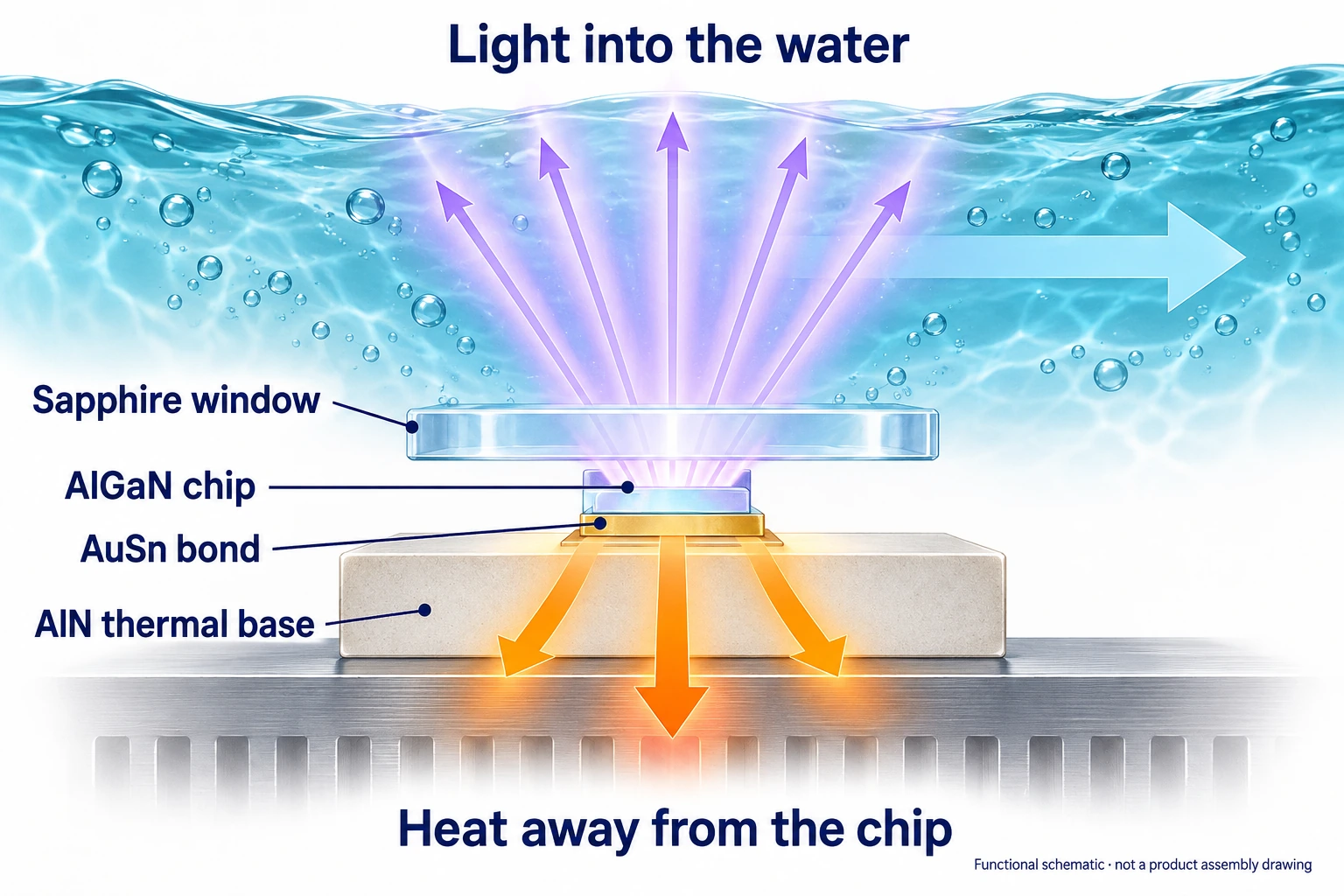
These details serve a practical purpose: the chip must generate useful radiation, the package must sustain it, and the reactor must expose the moving water to it. Wall-plug efficiency (WPE), thermal management, and optical coupling therefore connect directly to dose delivery and service life.
UVC LEDs also support instant switching and flow-activated operation. Agua Topone models use model-specific L70 service bases of approximately 3,000–5,000 active operating hours; L70 describes output maintenance at 70% of initial output. The AGLED-40012 lists a 5,000-hour basis and a replaceable LED assembly that allows service while retaining the reactor body. [4][5]
Why Should Filtration Come Before UV?
Prefiltration removes material that can obstruct UV treatment, while the downstream UV stage inactivates microorganisms that remain in the water. The CDC specifically notes that UV systems with prefiltration work better than systems without it. [1]
A common treatment sequence is:
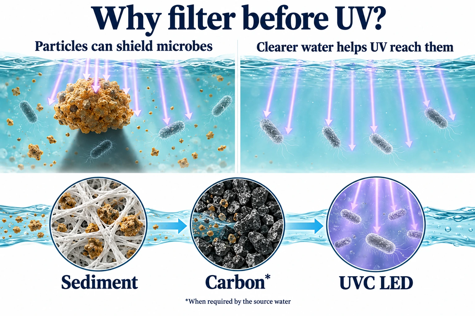
Two effects explain the value of this arrangement. First, suspended particles can shield microorganisms from the light. Second, dissolved UV-absorbing substances—such as natural organic matter or iron-related constituents—can absorb radiation before it reaches the target organisms. Different source waters therefore need different pretreatment.
UV transmittance: how much light passes through the water
Ultraviolet transmittance, or UVT, measures the percentage of UV light that passes through water over a stated optical path. Engineers commonly report a 1 cm path length and must identify the measurement wavelength. Water that transmits light well at one wavelength may behave differently at another. [3]
The Beer–Lambert relationship explains how absorption affects the light path. Agua Topone's sizing guide illustrates a change from 95% to 85% UVT, which lowers the average 1 cm transmittance factor from approximately 0.975 to 0.923—a reduction of about 5.4% before fouling or source aging enters the calculation. [6]
Consequently, a sediment cartridge and a carbon cartridge do more than improve appearance or taste. Where they address the source water's particles and UV-absorbing contaminants, they help the UV reactor deliver its intended treatment.
UV dose: intensity multiplied by exposure time
The basic dose relationship is:
D = I × t
Here, D is dose in mJ/cm², I is irradiance in mW/cm², and t is exposure time in seconds. In the same reactor, increasing flow generally shortens exposure time. Meanwhile, lower UVT, optical fouling, or reduced LED output lowers the available irradiance. [3]
A short engineering example makes the connection tangible. The AGLED-40012 publishes 40 mJ/cm² at 12 GPM, with 50 W input and 2,000 mW UVC radiant output. The following screening calculation uses that product reference and the sizing guide's explicit assumption of 95% reference UVT. [5][6]
| Illustrative operating case | Flow and assumptions | Screened UV dose |
|---|---|---|
| Lower flow with reference optical conditions | 8 GPM; reference UVT; no aging or fouling derating | 40 × (12/8) = 60.0 mJ/cm² |
| Lower UVT plus aging and fouling | 8 GPM; 85% UVT; transmittance ratio 0.947; aging factor 0.70; fouling factor 0.90 | 40 × (12/8) × 0.947 × 0.70 × 0.90 ≈ 35.8 mJ/cm² |
| Restore UVT alone | 8 GPM; 95% UVT; retain the same aging and fouling factors | 40 × (12/8) × 0.70 × 0.90 = 37.8 mJ/cm² |
This example shows why filtration, flow control, cleaning, and source maintenance work together. Restoring UVT alone does not cancel the other losses. With the degraded optical assumptions above, the screening equation places the allowable flow at approximately 7.16 GPM, conventionally rounded to 7.2 GPM. Actual reactor acceptance uses its applicable validation data.
For the complete calculation and selection workflow, see how to size a UVC LED water sterilizer by flow rate and UVT (opens in a new tab).
How Do Standards and Tests Verify UV Performance?
Filter evaluation starts with the contaminant-removal claim. UV evaluation adds another question: does the reactor deliver the treatment required for the target microorganism at the specified flow and water conditions? Standards, optical-hydraulic design, microbial tests, and durability checks answer different parts of that question.
NSF and EPA: understand the treatment objective
NSF/ANSI 55 distinguishes Class A, associated with a 40 mJ/cm² benchmark for disinfection, from Class B, associated with 16 mJ/cm² for supplemental bactericidal treatment of water that health authorities already consider acceptable. These classifications describe different treatment duties. [7]
EPA's municipal UV guidance gives organism-specific dose requirements. Its Table 1.4 lists 11 mJ/cm² for 3-log Giardia inactivation, 12 mJ/cm² for 3-log Cryptosporidium inactivation, and 186 mJ/cm² for 4-log virus inactivation, reflecting resistant viral targets such as adenovirus. A 3-log reduction equals 99.9%; 4-log equals 99.99%; and 5-log equals 99.999%. [3]
The EPA values belong to their stated regulatory and validation framework. They explain why the organism, light spectrum, and operating envelope matter when engineers assess a UV system; they do not create one universal dose for every application.
CFD: follow the water and the light
Computational fluid dynamics, or CFD, models water movement through the chamber. A water parcel that follows a fast route can receive less exposure than one that stays longer. Engineers therefore study the distribution of exposure, rather than relying only on the reactor's total volume.
Agua Topone's engineering guide describes Navier–Stokes flow calculations, k–ε turbulence modeling, and Lagrangian particle tracking alongside the Discrete Ordinates radiation model. Together, these tools map velocity, mixing, individual trajectories, water absorption, and optical interactions with the chamber. Tangential inlet design and reactor geometry help engineers improve the distribution of treatment. [8]
In plain language, the model asks whether water can pass through too quickly or follow a poorly illuminated route. That question links the stainless-steel chamber design directly to microbial performance.
Biological testing: measure the treatment outcome
Biodosimetry complements simulation with experimental evidence. The process compares a challenge organism's reduction through the reactor with its measured UV dose-response curve to determine a reduction equivalent dose (RED). A microbial challenge test also directly records the organism reduction under its specified conditions. [3][8]
Agua Topone provides concrete third-party results. SGS reports greater than 99.999% total-coliform reduction in E. coli ATCC 25922 challenge tests for both AGLED-12G and AGLED-40012 at 50 L/min at startup of operating life. The respective reports are NBF25-0021833-01 and NBF25-0011031-01. Both models occupy the published 12 GPM / 45 L/min product class. [9][10][15]
These results connect the principle of UV inactivation with actual reactor testing. For product assessment, read the microbial report alongside the selected model's electrical, optical, hydraulic, and compliance documents. A CE conformity document and an SGS microbial test report serve different assessment purposes.
Reliability testing: sustain performance in real equipment
A reactor must also withstand pressure, environmental exposure, and electrical stresses. Agua Topone's flow-rate engineering guide describes mechanical and electrical stress testing in ISO 17025-accredited laboratories, including 10,000 pressure cycles up to 1.04 MPa and 24 hours of dry operation. [8]
The company also publishes separate model-specific factory test items and acceptance criteria. For example, AGLED-12G includes a 24-hour powered dry-operation test and 100,000 pressure cycles at 0–0.45 MPa. [11]
AGLED-40012's published criteria include 10,000 pressure cycles at 0–0.45 MPa, a 1,500 V AC dielectric withstand test for one minute, freezing and thermal-shock tests, humidity exposure, vibration, and drop testing. [5]
Each test addresses a different failure mechanism: leakage, electrical insulation, thermal stress, transport damage, or control reliability. Together with microbial testing, these checks explain why selecting a UV stage involves more than comparing electrical wattage.
Should You Choose a Standalone UV Reactor or an Integrated System?
Once the treatment roles are clear, the hardware choice becomes easier. Start with the source-water needs, existing equipment, and actual peak flow.
Add UV to an existing filtration system
If a home or facility already has suitable pretreatment, a standalone reactor adds a dedicated disinfection stage downstream. Agua Topone's AGLED-40006 serves the 6 GPM / 23 L/min class. The AGLED-12G and AGLED-40012 serve the 12 GPM / 45 L/min class, with published electrical-input/UVC-output pairs of 16 W / 500 mW and 50 W / 2,000 mW, respectively. [5][11]
The AGLED-12G uses a slim 304 stainless-steel body and a status ring: white for standby, blue for active disinfection, and red for a fault. The AGLED-40012 provides a replaceable LED assembly and runtime/status information for planned service. Match the reactor to the project's treatment requirement as well as its plumbing layout.
Put compact UV near the drinking-water outlet
An RO membrane treats water upstream, but a storage tank and dispensing line remain downstream. A compact point-of-use UV module adds treatment close to the final outlet, where it can inactivate microorganisms in the water immediately before dispensing.
Examples include EC-11 at 1.5 L/min, EC-13 at 2 L/min, and EC-10, EC-12, or AGLED-40002 at 4 L/min. Keep the tank and tubing sanitary as well: flowing-water UV treatment does not remove an established biofilm from the surrounding plumbing. [4][9]
Combine filtration and UV in one platform
For a new installation, an integrated system brings the treatment stages into one coordinated layout. Agua Topone's VPS and GPS families combine PP sediment filtration, CTO carbon filtration, optional GAC, and UVC LED disinfection. GPS configurations use the AGLED-12G; VPS configurations use the AGLED-40012. [12][13]
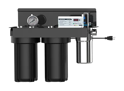
The VPS-103/104 10-inch configurations list 30 L/min at 30 mJ/cm², while the VPS-203/204 20-inch configurations list 45 L/min at 30 mJ/cm². These system-level selections account for the integrated platform, rather than simply repeating a standalone reactor's flow label. [12]
For filtration and UV in one assembly, compare the VPS multi-stage filtration and UVC LED systems (opens in a new tab) and their application requirements.
Finally, plan maintenance for both functions. Replace loaded cartridges, maintain optical performance, and follow the model's service instructions. The AGLED-40012 retains its reactor body during LED replacement, but its procedure still requires electrical isolation, water shutoff, depressurization, and draining. UV also leaves no disinfectant residual to protect downstream storage and distribution. [3][14]
Choose filtration for the contaminants you need to remove and UV for the microbial inactivation you need to achieve. Share your source-water information, pretreatment, peak flow, and treatment target with Agua Topone to select a standalone module or an integrated system.
Frequently Asked Questions
Can UV disinfection replace a sediment or carbon water filter?
No. UV inactivates microorganisms but does not remove sediment, chlorine, dissolved salts, or heavy metals. Sediment and suitable carbon filters perform the removal stages, while the UV reactor supplies disinfection. A combined system uses both functions.
Should the UV reactor go before or after filtration?
Place UV after the pretreatment that the source water and reactor require. Upstream sediment filtration reduces particle shielding, while suitable additional treatment addresses UV-absorbing substances and fouling. This arrangement helps light reach microorganisms inside the UV chamber.
Why add UVC LED treatment after reverse osmosis?
A downstream UVC LED module adds microbial treatment near the final drinking-water outlet. This position addresses microorganisms in water leaving the RO storage tank and dispensing line. Continue to clean and maintain those components, because UV treatment of flowing water does not remove an established plumbing biofilm.
Sources and Further Reading
- CDC — About Home Water Treatment Systems (opens in a new tab)
- NSF — Standards for Water Treatment Systems (opens in a new tab)
- U.S. EPA — UV Disinfection Guidance Manual, mechanisms, Table 1.4 and reactor validation (opens in a new tab)
- Agua Topone — UVC LED technology: chip, package, optical and thermal design (opens in a new tab)
- Agua Topone — AGLED-40012 specifications and factory acceptance criteria (opens in a new tab)
- Agua Topone — Flow-rate and UVT sizing: worked screening calculations (opens in a new tab)
- ANSI — NSF/ANSI 55 UV treatment classifications (opens in a new tab)
- Agua Topone — Flow, CFD, biodosimetry and reliability engineering guide (opens in a new tab)
- Agua Topone — Model-specific SGS report directory (opens in a new tab)
- SGS — AGLED-40012 report NBF25-0011031-01, 25 June 2025 (opens in a new tab)
- Agua Topone — AGLED-12G specifications and factory acceptance criteria (opens in a new tab)
- Agua Topone — VPS configurations and system flow-by-dose table (opens in a new tab)
- Agua Topone — GPS filtration and UVC LED configurations (opens in a new tab)
- Agua Topone — AGLED-40012 module replacement procedure (opens in a new tab)
- SGS — AGLED-12G report NBF25-0021833-01, 20 October 2025 (opens in a new tab)