
Centralized water supply
Add UV disinfection to a treated-water supply line, with capacity matched to normal and peak demand.
Industrial water treatment / MegaUV series
MegaUV industrial UV water treatment systems use UVC LEDs for centralized supply, pretreated process water and OEM treatment lines. Choose from five capacities covering 15–150 t/h.
Nominal series capacity
UVC LED wavelength
Working pressure
Process applications
MegaUV integrates UVC LED disinfection into centralized water supply, process-water and packaged treatment systems. Specify the duty from water quality, operating flow and the required disinfection target.
Treatment to meet inlet-water requirements
Water passes through the UVC LED reactor
Treated-water supply or point of use
Add UV disinfection to a treated-water supply line, with capacity matched to normal and peak demand.
Specify the reactor around process-water quality, temperature and material compatibility.
Coordinate the reactor, cabinet and interfaces within a packaged water-treatment system.
Partner-supplied UVC LED installations showing parallel-unit integration.
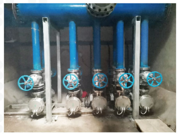
50 t/h × 5 units in parallel
Drinking-water disinfection for an industrial park.

30 t/h × 3 units in parallel
UV disinfection within a purified-water preparation system.
01 / Thermal management
A dedicated pump circulates water through the LED cooling circuit. Thermal management is built into the reactor assembly, with cooling specified for inlet temperature and material compatibility.
02 / Monitoring & control
Monitor key operating parameters through a dedicated control cabinet, with a passive dry-contact interface for coordinated start and stop.
Automatic shutdown above 60°C. Restart is manual after the condition clears.
03 / Installation & service
The supported stainless-steel reactor connects to the treatment line through flanged ports. Plan the reactor position, cabinet location and maintenance clearance together.
LED modules are removed for cleaning. The service procedure and cleaning interval follow the supplied configuration, water quality and operating conditions. Use technical support to confirm model-specific installation inputs, and OEM / ODM project review for custom integration.
Engineering selection
Match flow, connections and electrical load to your treatment line. Nominal capacities apply at UVT ≥93% at 275 nm, measured over a 10 mm optical path. Read the UVT measurement guide and flow-rate and UVT sizing guide before selecting a capacity.
Swipe or scroll to view all columns →
| Model | Nominal flow t/h | Rated power W | Connection | Reactor outline L × W × H, mm | Engineering drawing |
|---|---|---|---|---|---|
| MegaUV-015 | 15 | 580 | DN80 | 980 × 260 × 450 | Request drawing |
| MegaUV-020 | 20 | 800 | DN80 | 980 × 260 × 450 | Request drawing |
| MegaUV-030 | 30 | 1,200 | DN80 | 980 × 260 × 450 | Request drawing |
| MegaUV-050 | 50 | 2,000 | DN150 | 1100 × 400 × 530 | Request drawing |
| MegaUV-150 | 150 | 6,000 | DN200 | 1500 × 600 × 800 | Request drawing |
The existing 5 and 10 t/h configurations are moving to an E-type replacement. Use the reference specifications below for early planning and contact us for the current supply configuration.
Swipe or scroll to view all columns →
| Reference model | Nominal flow, t/h | Rated power, W | Connection | Reactor outline, mm |
|---|---|---|---|---|
| MegaUV-005 | 5 | 310 | DN65 | 876 × 238 × 365 |
| MegaUV-010 | 10 | 500 | DN65 | 876 × 238 × 365 |
Dimensions & installation
These reference sheets are labeled by flow group, not individual MegaUV model code. Request the selected model’s installation drawing, flange details and service clearance. For 150 t/h, request a project drawing.
Technical specifications
Choose a category below to view its specifications.
Compare the model specifications with your flow and installation requirements. Water-quality and temperature conditions are listed with the relevant values.
UVT ≥93% is specified at 275 nm over a 10 mm optical path. Include both wavelength and path length with your water analysis. A reading taken at another wavelength is not directly interchangeable.
40 mJ/cm² is the manufacturer’s nominal dose at the specified UVT. Request the selected model’s test report for performance verification.
Rated LED life is L70 ≥20,000 h at an LED pin temperature ≤45°C. L70 means 70% of initial light output; it describes LED output, rather than whole-system service life.
For project verification, request a report identifying the reactor model, test organism, flow, water quality, method and operating conditions. Our testing and validation guide explains how to review the evidence.
Project planning
Start with normal and peak flow, UVT at 275 nm over a 10 mm path, water temperature and the treatment target. The nominal range uses UVT ≥93%. Lower-UVT water needs a project-specific sizing assessment. Follow the sizing workflow; no flow derating is assumed from the nominal label alone.
The standard system uses a 50 Hz cooling pump. A 60 Hz pump can be customized. Tell us the destination voltage and frequency so the complete electrical configuration can be specified for the project.
Confirm the selected model, flange details, available pipework space, cabinet position and maintenance clearance. The standard cabinet cable is 5 m. Use a project-approved drawing for installation; the LDS17 reference drawings shown above identify flow groups and require confirmation for the ordered model.
For the MegaUV nominal capacity condition, report UVT at 275 nm over a 10 mm path. Send the measured value, wavelength, path length and sample location. UVT254 measured over 1 cm is a common reference, but it cannot be substituted directly for the specified UVT275 value. See how UVT is measured.
No. The stated 40 mJ/cm² is a manufacturer rating. Verified performance is tied to the reactor model, test organism, flow, water quality and operating conditions. Review the specification basis and request the selected model’s test report.
Standard functions monitor UV intensity, temperature and operating time, with an indicator-light general alarm and one passive dry-contact start / stop interface. Temperature above 60°C triggers shutdown; restart is manual after the condition clears.
Flow metering and interlocks are optional. Pump-stop and valve-close coordination require custom system integration. Confirm the required response and supplied I/O scope during project review.
Start your project
Share your application, flow and water conditions. We’ll help define the reactor, cooling arrangement and control scope for your installation.