How to Size One UVC LED System for a Coffee Machine and an Ice Maker
Yes, one UVC LED system can serve both a coffee machine and an ice maker. Size it for their combined peak inlet flow, then check the smallest refill, water quality and working pressure. The key is the water both appliances draw at the same time—not their average daily consumption.
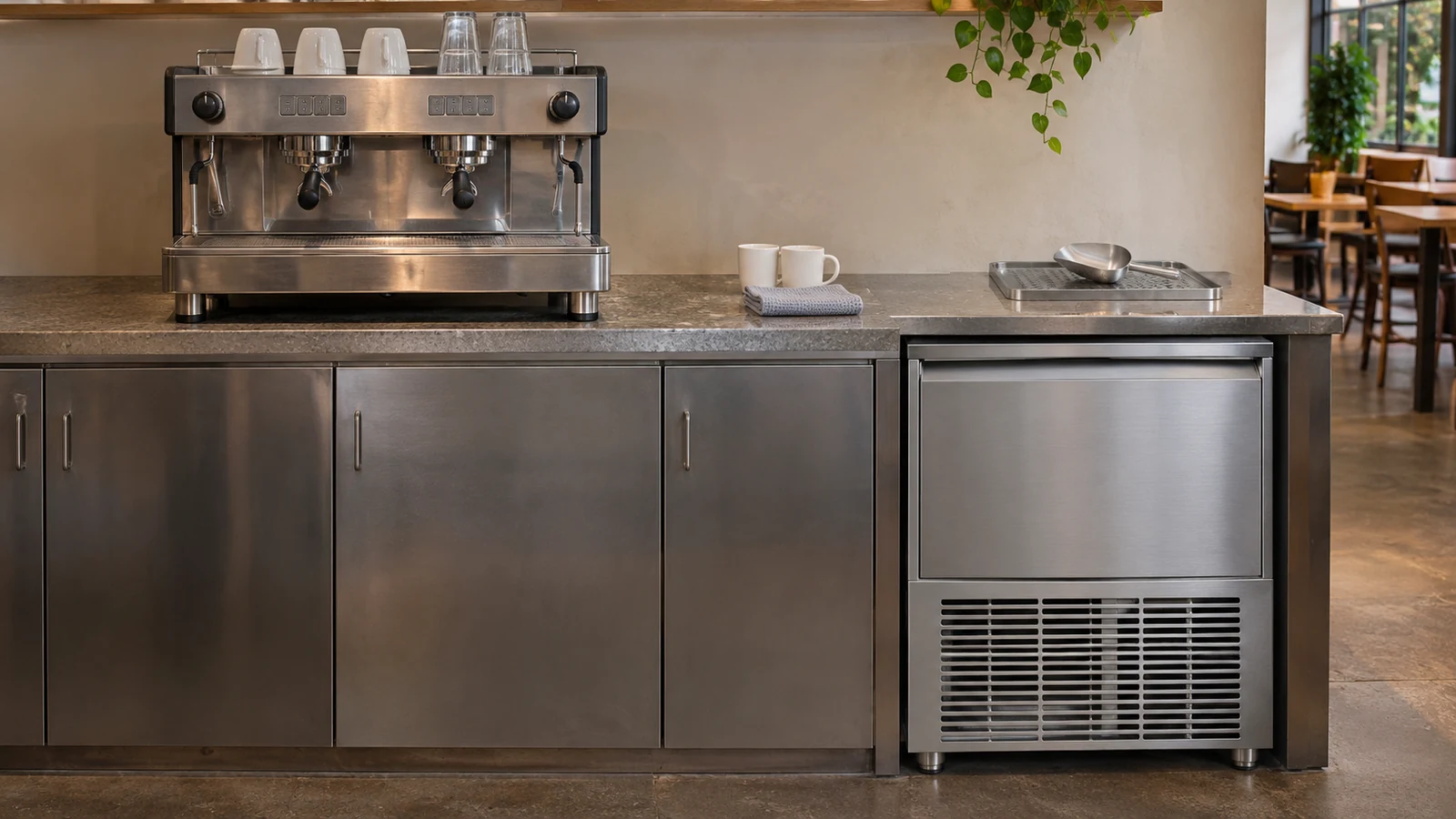
Picture the morning rush: the coffee machine refills its boiler just as the ice maker opens its inlet valve. A shared treatment line saves space, but it must handle that overlap. An on-demand UVC LED system also suits the pauses between orders, switching on when water flows.
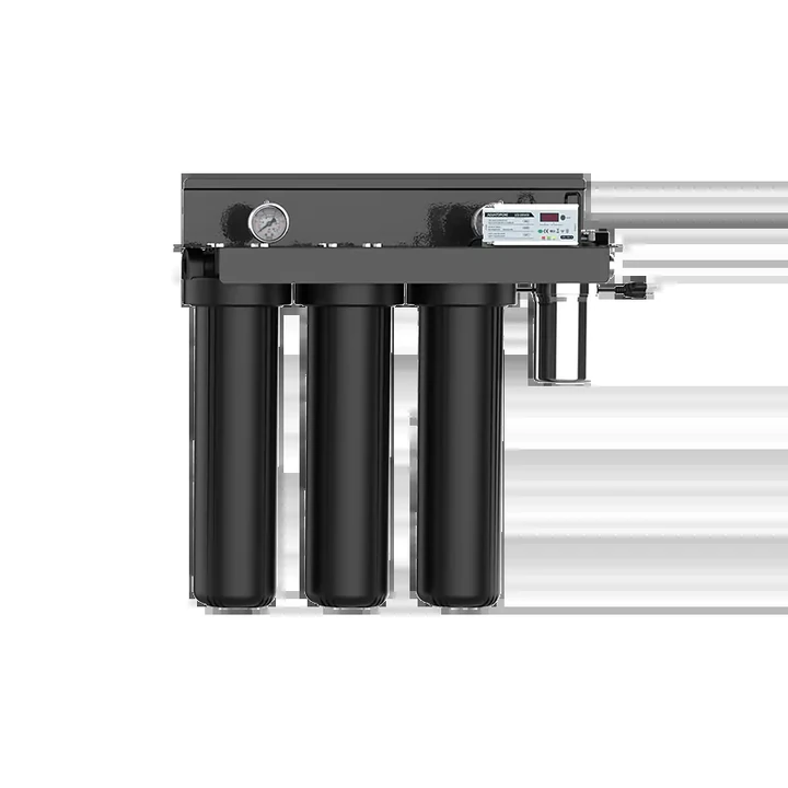
Agua Topone helps coffee and ice equipment manufacturers, water-treatment integrators and project buyers select UVC LED treatment for their water paths. We review shared or separate-branch layouts, match peak flow and activation requirements, and provide model-specific technical documents and OEM/ODM integration support.
Why does simultaneous refill flow matter?
Coffee and ice machines draw water in cycles. Boiler replenishment, rinsing and ice-maker reservoir refills create short inlet-flow bursts. If those events overlap, more water passes through the shared UV chamber. Exceeding its treatment rating reduces exposure time and can compromise disinfection.
A typical shared layout places the UVC LED stage after suitable pretreatment and before the supply divides between the coffee machine and ice maker.
If coffee and ice need different mineral profiles, separate the treatment branches earlier. Where a storage tank is used, consider a final UVC stage after storage to treat the water closer to the appliances.
One shared unit or two dedicated modules?
| Selection point | One shared UVC LED unit | Two branch UVC LED modules |
|---|---|---|
| Best fit | Both appliances use the same treated-water supply. | Different water profiles, flow ranges or integration needs. |
| Flow sizing | Cover the combined refill peak and the smallest individual draw. | Match each module to its appliance’s operating range. |
| Installation | One treatment point before the manifold; fewer UV connections. | Two treatment points, with separate space and control requirements. |
| Maintenance | One UV service point simplifies routine upkeep. | Each branch can be serviced separately when isolation is provided. |
| Pressure | Check both appliance inlets during simultaneous refill. | Check each branch and the shared upstream supply under load. |
For intermittent beverage demand, UVC LEDs offer instant-on operation and compact integration. Conventional UV lamps remain an option for suitable systems; compare the selected models’ operating schedules, standby water heating and service needs. Agua Topone’s 0.1-second instant-start, cold-light-source technology supports on-demand treatment and helps limit standby water warming.
How do you size the system in four steps?
Step 1: Find each appliance’s actual inlet demand
Start with the exact appliance manuals, then measure inlet flow and dynamic pressure during refills, initial filling and relevant restart cycles. Cups per day and kilograms of ice per day describe production, not the flow through the UV chamber.
Check the manufacturer’s required supply capacity too. La Marzocco USA’s water specification, for example, lists a suggested mains supply of 8 L/min at 45–80 psi. Supply recommendations and actual inlet draws serve different purposes; both belong in the review. On water-cooled ice makers, distinguish ice-making water from condenser cooling water, as shown in the Hoshizaki KM-1300 series manual.
Step 2: Add the flows that can occur together
Here, is the peak shared flow; and are the coffee-machine and ice-maker inlet flows; covers any other simultaneous draws. Use the same flow units throughout.
Assume independently controlled appliances can refill together. Add a design allowance suited to the project’s supply conditions.
| Calculation | US GPM | Approx. L/min |
|---|---|---|
| Coffee-machine refill | 0.8 | 3.0 |
| Ice-maker refill | 0.7 | 2.6 |
| Combined peak | 1.5 | 5.7 |
| With an illustrative 20% allowance | 1.8 | 6.8 |
The 20% allowance is an example, not a universal rule. This duty exceeds a 4 L/min module, so review a higher-flow system or separate branch treatment. Our flow-rate sizing guide explains the relationship between flow and UV exposure.
Step 3: Check the smallest refill
Peak capacity is only half the check. A flow-activated module must also start during a small top-up. AGLED-40002 has a published startup flow above 0.5 L/min. A 0.3 L/min refill is below that threshold.
For example, a smaller system drawing 1.2 L/min for coffee and 2.0 L/min for ice totals 3.2 L/min—within a 4 L/min maximum. But a 0.3 L/min top-up still needs a different suitable activation arrangement. Verify the selected module and controller during short pulses, first-water delivery and repeated starts.
Step 4: Match water quality and working pressure
Choose PP sediment, GAC or CTO carbon pretreatment for the source water and appliance needs. Sediment filtration helps reduce particles, while suitable carbon media can reduce some UV-absorbing substances. Check UV transmittance (UVT) after pretreatment against the selected reactor’s requirements.
Measure pressure while both appliances refill. Filters, tubing, valves and the reactor all affect the available pressure. Check the complete line, including filters near their service limit. UVC treatment does not remove minerals, so retain the water-chemistry controls required for coffee and ice.
Which Agua Topone module fits the flow?
Use the published flow classes to build a shortlist, then match activation, connections, voltage and pressure to the installation.
| Model | Published maximum flow | Selection focus |
|---|---|---|
| EC-11 | 1.5 L/min | Lower-flow appliance branches. |
| EC-10 / EC-12 | 4 L/min | Match the exact version and control arrangement. |
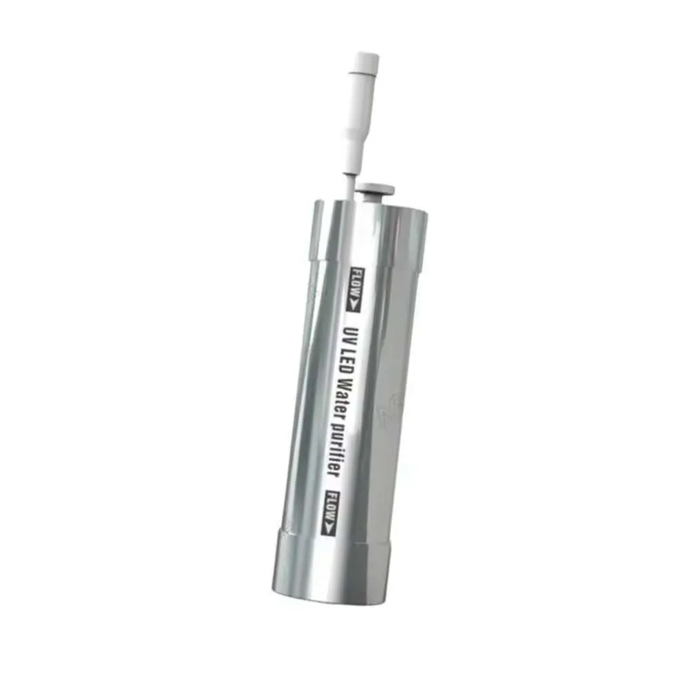
| AGLED-40002 | 4 L/min | Check the startup threshold as well as peak flow. |
AGLED-40002 combines a Ø38 × 129 mm body, 1/4-inch quick-connect ports and rated input power . It is available in separate 12 V DC and 24 V DC versions, with a maximum inlet pressure of 0.8 MPa (8 bar). Leave room for tubing bends, wiring and servicing.
How would separate branches handle the 6.8 L/min example?
Using the same assumed refill flows and illustrative 20% allowance, size each branch separately:
- Coffee branch:
- Ice-maker branch:
Both calculated duties fall below AGLED-40002’s published 4 L/min maximum, making one AGLED-40002 on each appliance branch a candidate configuration to evaluate. Place each unit after the supply splits so it treats only its assigned appliance. Confirm activation during the smallest refill, water quality and working pressure on both branches; the shared upstream supply still needs to support simultaneous demand.
This gives the example a practical selection route: evaluate two compact branch modules, or review a higher-flow system if one shared treatment point is preferred. Compare the AGLED-40002 engineering data with the appliance requirements, and ask our team to review the layout and control configuration.
What performance and manufacturing support are available?
SGS-tested performance at the model’s rated flow
AGLED-40002 achieved total-coliform removal at 4 L/min in SGS report NBF25-0016420-01, using E. coli ATCC 25922 at the startup of operating life. The report records an influent count of and an effluent result of . This model-level test supports selection; the coffee-and-ice examples above illustrate sizing.
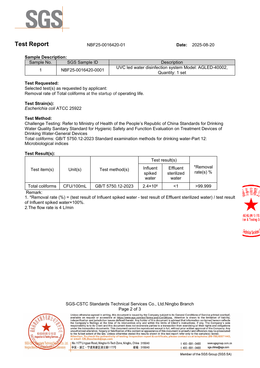
Open the complete SGS report or visit Testing & Validation for the supporting documents.
Clean chambers and clearer service planning
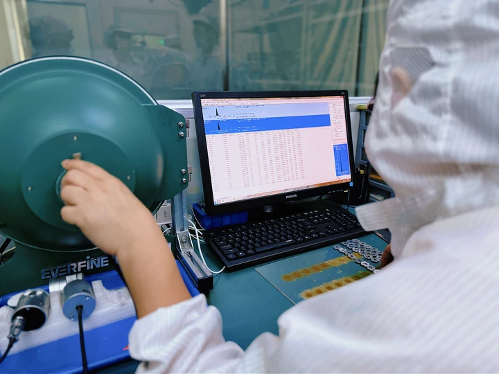
Agua Topone uses ultrasonic cleaning for stainless-steel chambers to help remove manufacturing oils and impurities. For compatible configurations, a smart driver with a 5,000-hour countdown records actual LED on-time, helping operators plan maintenance around intermittent use. Serviceable module designs simplify replacement. See our L70 lifespan and smart-driver guide for configuration details.
What can an actual installation show?
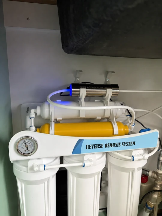
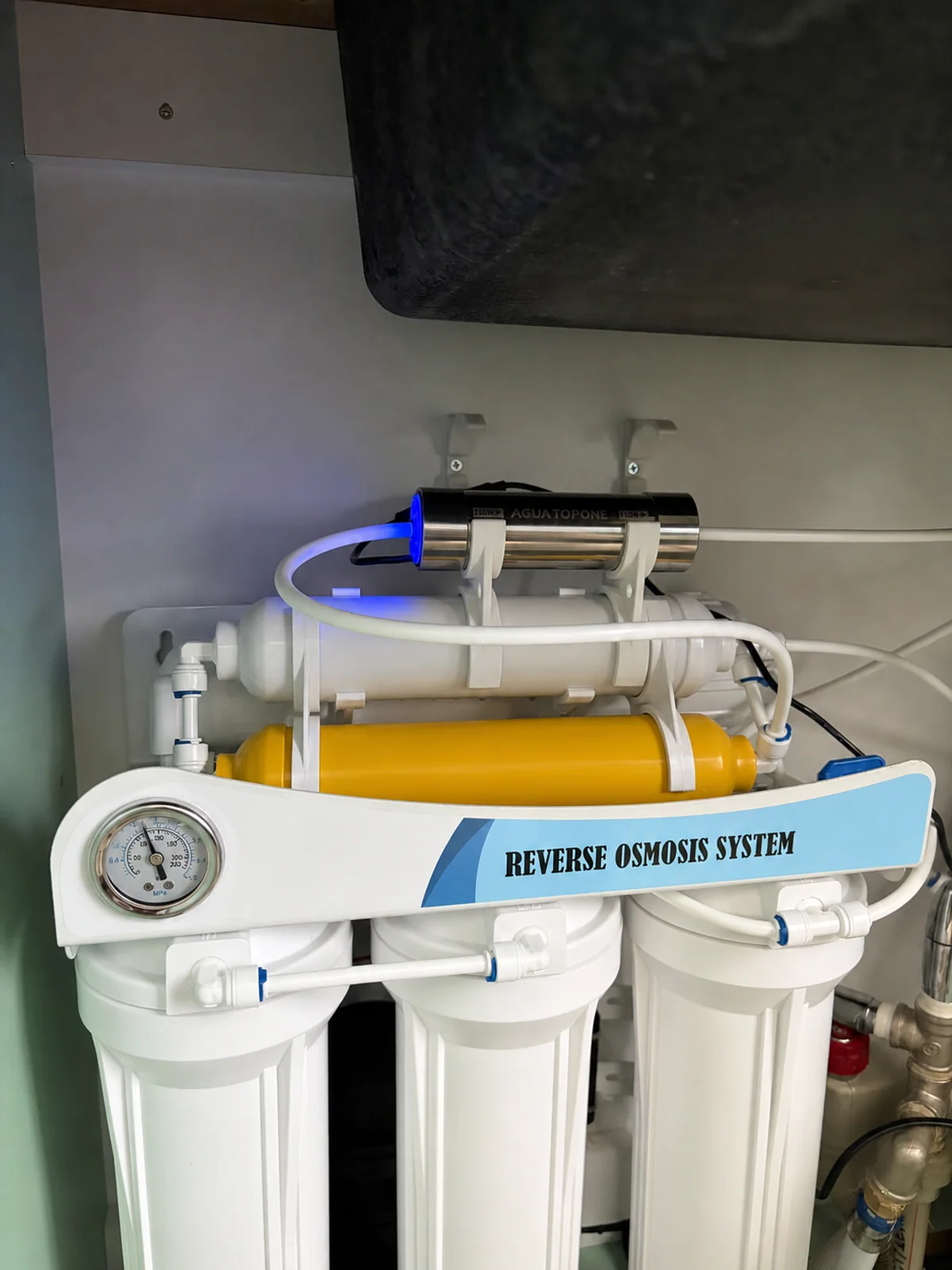
Our Bulgarian under-sink RO installation shows AGLED-40002 mounted above the filter assembly, using the cabinet’s upper space while keeping filter housings accessible. It provides a useful mounting reference for the same model; a beverage installation adds its own manifold and appliance connections.
What should you check before handover?
Run each appliance separately, then trigger simultaneous refills. Record inlet flow, dynamic pressure and UVC activation during the smallest top-up. Repeat relevant restart cycles and confirm the installed voltage version and controller. Complete the required water-quality and microbiological checks at the agreed sampling points.
Keep downstream tubing, reservoirs and ice-contact surfaces on the appliance’s cleaning schedule. UVC treats water passing through the reactor; it does not leave a disinfectant residual in the branch lines.
Frequently asked questions
Will one shared UVC LED unit warm the ice-maker supply?
On-demand UVC LED operation helps limit standby water warming between refill cycles. Check inlet temperature during commissioning, particularly near hot coffee-machine components.
Where should the shared unit be installed?
Usually after suitable pretreatment and before the tee supplying both appliances. With storage, review a final treatment position after the tank. Keep the downstream pipework short and serviceable.
How often should the module be replaced?
Follow the selected model’s service instructions. A compatible 5,000-hour smart driver tracks actual LED operating time and provides a maintenance reminder; calendar intervals depend on daily use and operating conditions.
Can a flow restrictor make a smaller unit suitable?
Only if both appliances still receive their required flow and working pressure. If restriction causes refill faults, choose a higher-flow system or review separate branches.
Build your beverage and ice-water solution with Agua Topone
Since 2006, Agua Topone has developed water-disinfection products for POU, POE and OEM applications. With 40+ national patents, 80+ export markets and a 10,000+ m² manufacturing facility, we support equipment integration, private-label development and project-specific selection.
Send us the appliance models, peak and smallest refill flows, working pressure, water-quality information and a simple water-path sketch. Add the available voltage, connections and installation space.
With these inputs, our team can recommend a shared or branch layout, shortlist the module and control configuration, and provide the relevant drawings, specifications and test reports. Where standard configurations do not fit, we can assess the OEM/ODM integration requirements.
Contact Agua Topone’s engineering team to discuss your coffee-machine and ice-maker project, or explore our OEM / ODM support.
Sources and supporting documents
- La Marzocco USA — water specification and appliance documentation.
- Hoshizaki — KM-1300 series manual, water-supply connections.
- Agua Topone — AGLED-40002 specifications and SGS report.
- Agua Topone — L70 lifespan, smart drivers and chamber cleaning.
- Agua Topone — Bulgarian under-sink RO installation.
- Agua Topone — company and manufacturing background.