
How Should OEMs Bench-Test a UVC LED Water Module Before Integration?
Your UVC LED sample has arrived. You connect the water line and the specified power supply, open the outlet, and see the expected indicator. Water flows without an obvious leak. Is it ready for your purifier or dispenser?
That first check is useful, but an open bench rarely reproduces the appliance's tubing, power supply, enclosure, or dispensing cycle. A structured bench test turns “it works” into a repeatable result: how the identified sample behaves, under which conditions, and what needs further verification before integration.
Start with the exact sample configuration, measure actual flow and electrical input, and test the intended draw cycle. Then repeat the relevant checks inside the prototype. Keep these functional results separate from microbiological performance evidence and finished-appliance certification.
A practical five-stage test plan
- Identify the sample and define what a passing result means.
- Establish a measured hydraulic and electrical baseline.
- Test the appliance's actual dispensing cycle.
- Repeat the relevant checks inside the prototype.
- Review factory and microbiological evidence before sign-off.
Stage 1 Identify the Sample and Define the Test
Before applying power or water pressure, decide what the test must establish. Are you checking the supplied interfaces, confirming flow activation, measuring pressure loss, or assessing operation in an enclosure? Each objective needs its own observations and acceptance criteria.
A useful functional conclusion might be: “Sample A operated according to its specified control behavior at the recorded supply, flow, and temperature conditions.” A claim about microorganism reduction requires a different test and evidence package.
Record the configuration you actually received
A base model name may cover several OEM options. Capture these details in the sample record:
- Identity: model, sample or serial number, hardware revision, and document revision.
- Electrical configuration: voltage version, supplied driver or controller, connector, and pin polarity.
- Water connections: fitting size, flow direction, mounting requirements, and permitted pressure and water temperature.
- Control and service arrangement: flow activation or host control, available status signals, and the parts intended for replacement.
For example, separate 12 V DC and 24 V DC versions are offered for several compact modules. That does not mean the sample on your bench accepts either voltage. For the selection process, see our 12 V vs. 24 V power supply guide.
Use the model differences to choose your test focus
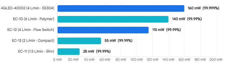
Model specifications: AGLED-40002 · EC-10 · EC-12 · EC-13 · EC-11
| Model | Published flow basis | Configuration feature | Useful bench-test focus |
|---|---|---|---|
| EC-11 | 1.5 L/min maximum design flow | Slim POU module; separate 12 V or 24 V DC versions | Actual draw rate, input at the module, and the supplied control interface |
| EC-12 | Up to 4 L/min model class | Integrated flow switch; voltage, connection, and optical-output options | Identify the variant and check activation during the intended draw cycle |
| AGLED-40002 | 4 L/min rated flow | Flow-triggered POU module; published startup flow >500 mL/min | Compare the appliance's lowest intended draw with activation behavior |
| AGLED-40012 | 12 GPM / 45 L/min maximum flow | Higher-flow POE reactor with a replaceable UVC LED assembly and separate driver | Driver installation, service clearance, and checks after approved replacement |
The flow entries describe their respective model specifications; they are not microbiological results under a shared test condition. AGLED-40012 also illustrates a serviceable POE architecture, with a different installation and power arrangement from the compact DC POU samples.
Keep the current drawing and instructions beside the rig. They determine filling, flushing, mounting, and the power-on sequence. Resolve unclear connections before testing, keep the reactor closed, protect electrical parts from water, and prevent direct UV-C exposure. Installation and technical support provides the route to model-specific guidance.
Stage 2 Establish a Measured Baseline
A good baseline lets another engineer understand the setup and repeat the result. Photograph the rig and label the source water, pretreatment, tubing, fittings, valves, measurement points, and module orientation.
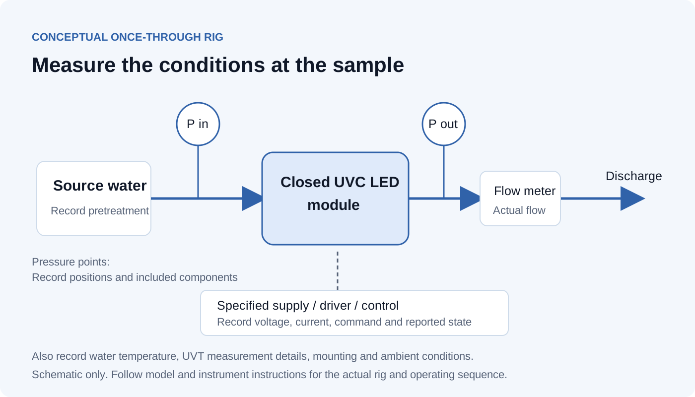
Measure flow and define the pressure boundary
Measure the water passing through the module with an instrument suited to the expected range. A pump setting or valve position cannot substitute for actual flow. Follow the meter's installation requirements and record its identification and calibration status.
If pressure loss affects the appliance, measure inlet and outlet pressure at the same operating flow. Record the fittings and tubing between the pressure taps: otherwise, their losses may be attributed to the reactor. Use the selected model's permitted operating conditions for the initial leak and function checks.
Measure electrical input at the sample
Record voltage at the module input while it operates, together with current and the measurement points. Measuring only at the power supply can miss a drop along the harness or connectors. For a sample supplied with a separate driver, distinguish the driver's input from its output and follow the approved connection method.
Electrical input power and UVC radiant output are different quantities. A value in optical milliwatts does not describe the electrical load on the appliance's power supply.
Keep water conditions in the record
Log the water source, temperature, pretreatment, and available water analysis. When UV transmittance is measured, record the UVT percentage, wavelength, and optical path length. Visually clear water does not establish UVT at the module's emission wavelength. Knight and colleagues' UV LED performance guidance explains why spectral measurement matters.
UVT may remain unmeasured during an initial functional check. Keep that gap visible when comparing the setup with a microbiological report.
Use a log that connects conditions to observations
Use one row for each defined run or cycle, supported by a master record for the rig and instruments.
| Record | What it explains |
|---|---|
| Sample ID, configuration, and document revision | Which hardware and instructions the result applies to |
| Voltage, current, and electrical measurement points | What power reached the sample |
| Flow, inlet and outlet pressure, and water temperature | The hydraulic operating point and pressure-loss boundary |
| Water source, pretreatment, and UVT details | How the test water compares with the relevant performance evidence |
| Ambient temperature, mounting, and temperature measurement point | The thermal conditions surrounding the assembly |
| Draw duration, cycle number, command, and reported state | How the sample responded during the intended use pattern |
| Expected behavior, observations, and unresolved items | Why the test passed, failed, or needs further investigation |
Write “not measured” or “not provided” for missing information. Retain raw logs and setup photographs, and identify changes in tubing, valves, power, or mounting before comparing runs.
Stage 3 Test the Actual Dispensing Cycle
A steady-flow run establishes a baseline. It does not answer every question about a dispenser that delivers short cup fills, pauses, and starts again.
UVC LEDs are instant-on light sources, which makes them useful for intermittent operation. The assembled system still depends on flow sensing, driver behavior, and appliance controls. Testing should therefore capture when water begins to move, when the module is commanded to operate, and what response the available signals show.
For a flow-activated sample
Observe flow starting, stabilizing, and stopping. Record the measured flow and the indicator or controller state throughout the sequence. If activation and deactivation thresholds are part of the plan, document the method used to increase and decrease flow.
AGLED-40002, for example, lists a startup flow greater than 500 mL/min. A slow-fill mode below that value needs review during selection; it should not be assumed to activate the module. The activation threshold describes control behavior, while microbiological performance needs its own supporting conditions. Do not apply this threshold to other models or bypass the supplied controls to force a result.
For a sample controlled by the appliance
Record the host command and available response signal on the same timeline. Identify whether the response represents a command state, driver status, fault, or an optical measurement. An “ON” command alone does not establish UVC output.
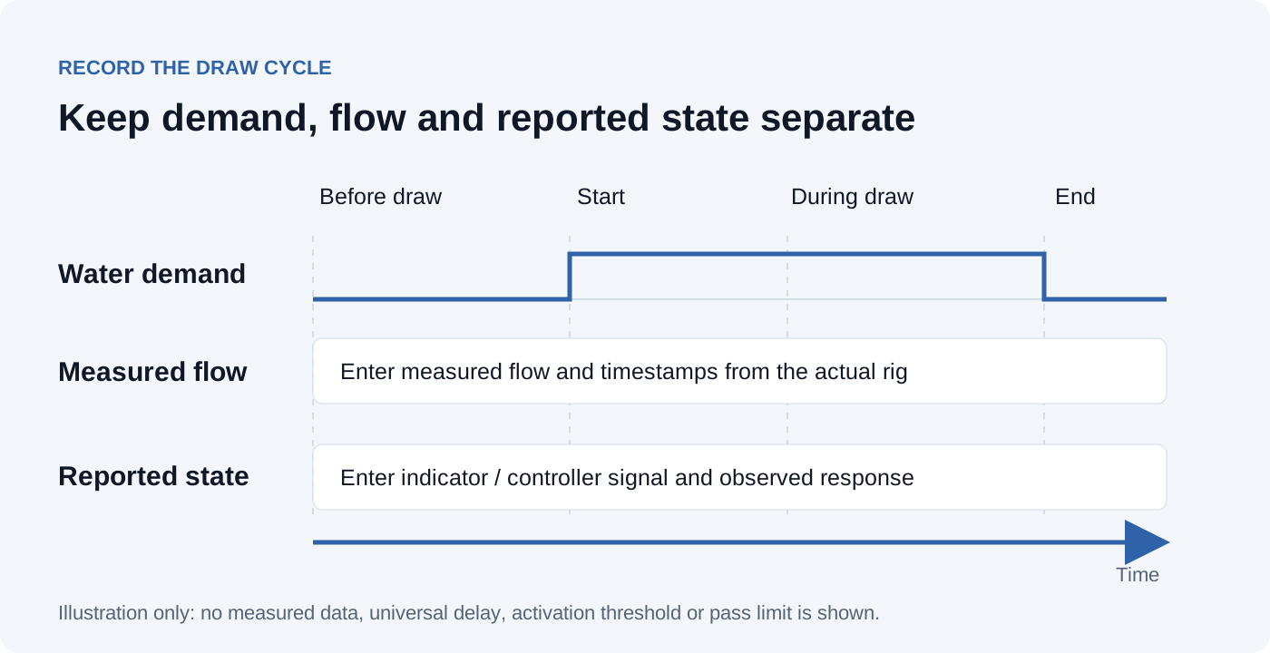
Build the cycle plan around the intended appliance use, including relevant short draws, repeated start-stop operation, and longer draws. Agree the duration and cycle count for the engineering question being tested. Use only permitted idle, no-flow, and continuous operating modes; dry operation, blocked-outlet tests, and fault injection require a separate approved procedure.
Stage 4 Repeat the Checks Inside the Prototype
Integration changes the conditions around the sample. Filters and nozzles can change flow and pressure loss; a shared supply can change voltage at the module; an enclosure can change heat removal.
Repeat the relevant baseline and cycle checks with the intended water path, harness, supply, brackets, and cabinet installed. If the module shares power with pumps or other loads, capture its input while those loads switch as they will in normal operation. Compare the lowest and highest intended dispensing conditions within the model's permitted range.
For thermal checks, define the measurement location, ambient conditions, mounting, operating cycle, and criterion for judging the result. A housing temperature is not an LED junction temperature. The ams OSRAM OSLON UV application note explains the component-level distinction; measurement points and limits for the assembled water module must come from its own technical instructions.
For a serviceable reactor, include access for the approved replacement procedure and the specified checks before returning the reassembled unit to service. Record the driver and replacement-part configuration alongside the reactor identity.
When an installed result differs from the open-bench baseline, compare the changed conditions first. A log showing a flow restriction, input-voltage dip, control delay, or enclosure-temperature change gives the supplier a concrete issue to investigate.
Stage 5 Review the Evidence Before Sign-Off
The functional log, factory reliability documents, and microbiological reports answer different questions. Review them together while keeping each conclusion within its scope.
Factory production checks: assembled systems and LED aging
At Agua Topone, factory testing covers assembled water treatment systems and LED aging. The photographs below show these two parts of production quality control.
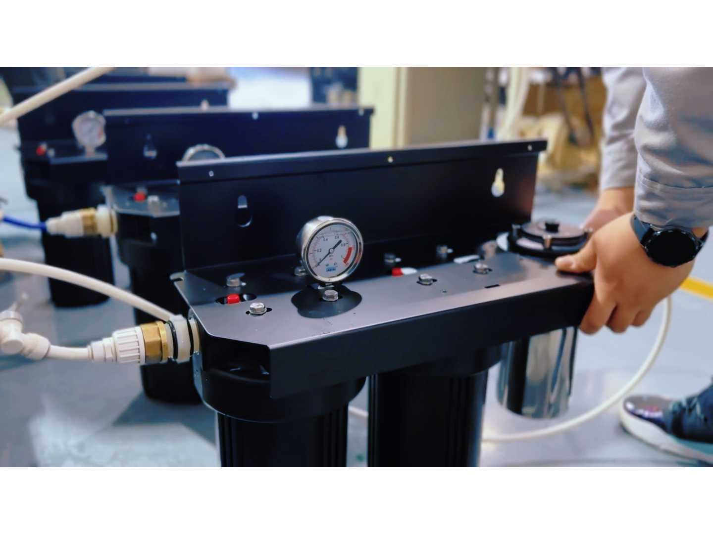
For LED aging, review the operating conditions and duration together with the associated optical measurements. Match the test record to the LED assembly supplied in your sample.
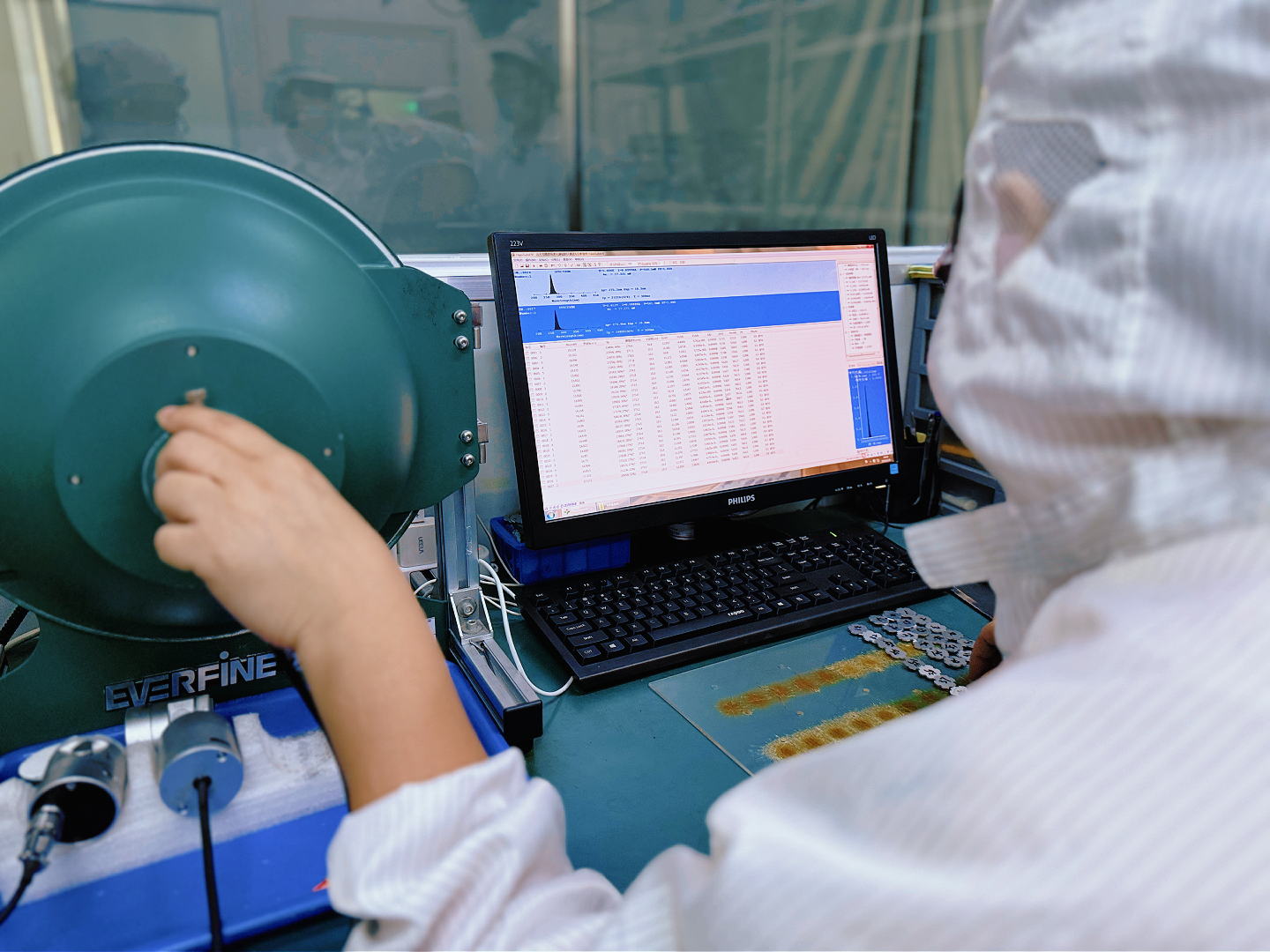
Factory verification examples with model-specific conditions
Factory reliability tests help assess sealing, pressure endurance, and other defined stresses. The following examples are published factory test criteria for the named models. They identify evidence to review with the supplier, rather than a universal procedure for incoming samples.
| Factory test item | EC-12 | AGLED-40002 |
|---|---|---|
| Static water-pressure resistance | Increase to 1.2 MPa within 5 minutes, at ≤0.4 MPa/s; hold for 15 minutes to check water tightness | Increase to 0.6 MPa within 5 minutes, at ≤0.4 MPa/s; hold for 15 minutes to check water tightness |
| Cyclic pressure | 10,000 cycles at 0–1.04 MPa, with a 2-second pressure rise, to observe water tightness | 10,000 cycles at 0–0.45 MPa, with a 2-second pressure rise, to observe water tightness |
EC-12 also lists a 24-hour powered test without water, with the criterion that the module remains undamaged and all functions remain available. This is a specific factory test item, not permission to run any sample dry in any enclosure.
Operating ratings remain separate: EC-12 lists a maximum inlet pressure of 1.0 MPa, while AGLED-40002 lists 0.8 MPa. Do not replace those ratings with a factory test pressure or transfer one model's procedure to another. For reliability review, request the applicable procedure, sample configuration, conditions, acceptance criteria, and results. The Quality and Manufacturing page gives context for the model and project inspection plan.
Match microbiological reports to the application
Start with Testing and Validation to locate the model-specific report. Review the tested configuration, organism, method, flow, water conditions, and operating state. Also establish what the evidence covers about operating cycles and service life. A reduction percentage alone cannot answer those questions.
If the intended appliance falls outside the report's conditions, identify the additional assessment or testing required. For new microbiological testing, agree the claim and protocol with a qualified laboratory, including the water matrix, challenge organism or surrogate, controls, sampling, replication, and reporting. A single outlet sample does not establish performance across the appliance's operating range.
Review certification by its stated purpose
A microbiological test report, a material-compliance document, and a finished-system certification are separate records. NSF identifies NSF/ANSI 55 as a standard for ultraviolet microbiological water treatment systems. Where certification is required, confirm the applicable standard, configuration, and listing route with the certification body. Documentation for a module does not automatically certify the finished appliance.
Make the Next Engineering Decision
Before moving to the next development stage, the team should be able to answer:
- Is the exact sample configuration traceable to the drawing and instructions?
- Were actual flow, pressure, electrical input, and relevant temperatures recorded?
- Did the control behavior match the intended dispensing cycle?
- Were the relevant checks repeated in the installed prototype?
- Do the reliability and microbiological documents apply to the selected configuration and conditions?
- Are unresolved issues, further tests, and certification responsibilities assigned?
The outcome may be to proceed with integration, resolve a specific interface issue, or obtain further performance evidence. Record that decision separately from approval of the final treatment claim.
For an Agua Topone sample review, share the sample configuration, rig photograph, measured conditions, cycle log, intended appliance use, and acceptance criteria. Include any mismatch between expected and observed behavior. Send your test package to our team so we can review the configuration, identify relevant documents, and discuss any OEM or ODM integration requirements.
Frequently Asked Questions
Does a normal indicator prove that the water is disinfected?
No. It confirms only the condition the indicator is designed to report. Use the model instructions to interpret the signal and separate performance evidence to assess microorganism reduction.
How long should the bench test run?
There is no single duration for every module or appliance. Define the objective, duty cycle, permitted conditions, and acceptance criteria. A functional check, thermal assessment, and lifecycle reliability test need different plans.
Can clear tap water be used for the first test?
It may be suitable if it meets the model's water requirements. Record its source and available analysis. Visual clarity does not establish UVT, and the result should not be transferred to a different water source without review.
Must we repeat every factory reliability test on arrival?
An incoming sample check and a factory qualification program serve different purposes. Agree which existing records can support the project and which tests need repeating for the appliance. Use dedicated, approved procedures for pressure overstress, dielectric withstand, dry operation, and environmental testing.
Sources and Technical Resources
- Model configurations and factory criteria: EC-11, EC-12, AGLED-40002, and AGLED-40012.
- Project documents: Installation and Technical Support, Testing and Validation, and Quality and Manufacturing.
- UV LED performance principles: Knight et al. 2023, Considerations for determining the performance of ultraviolet light emitting diode fluid disinfection systems.
- Component thermal principles: ams OSRAM, OSLON UV application note AN155.
- System certification scope: NSF, Ozone and UV Systems.