

12 V or 24 V? Specifying the Power Supply for an OEM UVC LED Water Module
When specifying a UVC LED water sterilizer for an OEM appliance, choose the voltage version that matches the appliance’s available DC supply and the module’s specified input. When both versions are available, 24 V reduces current and wiring losses at the same electrical input power; 12 V can simplify integration into an existing 12 V system. The final choice depends on supply capacity, harness resistance, and control requirements.
Consider an appliance that already has a 24 V power supply. The proposed UVC LED module is listed as “12/24 V.” Can the engineering team connect the sample directly?
That depends on what the specification means. It may describe two separately configured products. Before reviewing cable size or ordering an adapter, establish which voltage version will actually arrive.
Adapter Input vs. Module Input: Define the Power Architecture
An adapter labelled “Input: 100–240 V AC; Output: 24 V DC” describes two separate electrical interfaces:
| Specification | What it describes | What the OEM needs to establish |
|---|---|---|
| Adapter AC input | The mains supply entering the adapter | Compatibility with the target market and appliance requirements |
| Adapter DC output | The supply leaving the adapter | Output voltage, available current, regulation, and protection |
| Module DC input | The power entering the UVC assembly | Required voltage version, permitted input range, polarity, and current demand |
The adapter’s broad AC input range does not establish a broad DC operating range for the module.
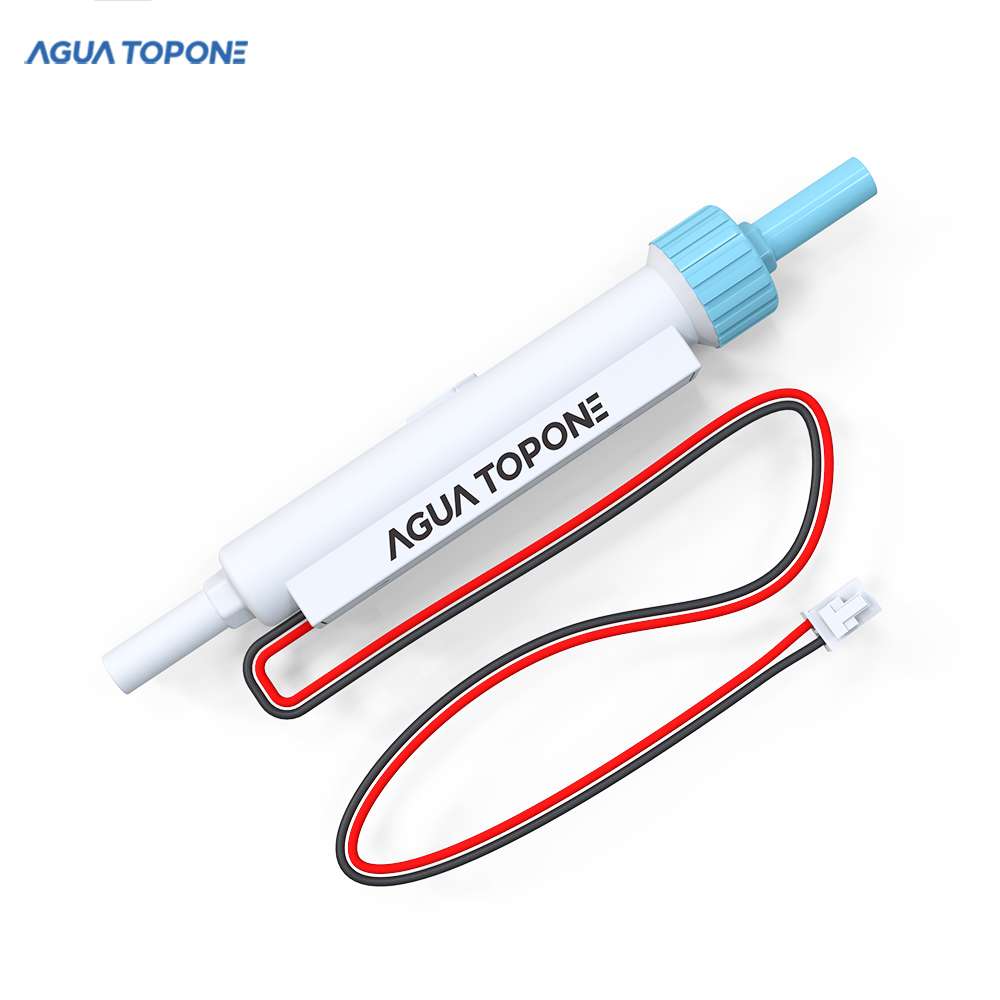
For example, Agua Topone’s EC-11 and AGLED-40002 specify separate 12 V DC and 24 V DC versions. Record the selected version on the quotation, sample label, wiring drawing, and production specification.
The supplied assembly also determines the required drive arrangement. A complete module may accept regulated constant-voltage DC and use internal circuitry to control LED current. A bare LED assembly may require a separate constant-current driver. These functions operate at different points in the power chain, as illustrated in MEAN WELL’s LED driver guidance.
For an assembly with an integrated driver, the arrangement can be represented as:
AC mains → AC/DC power supply → regulated DC input → internal LED driver → UVC LEDs
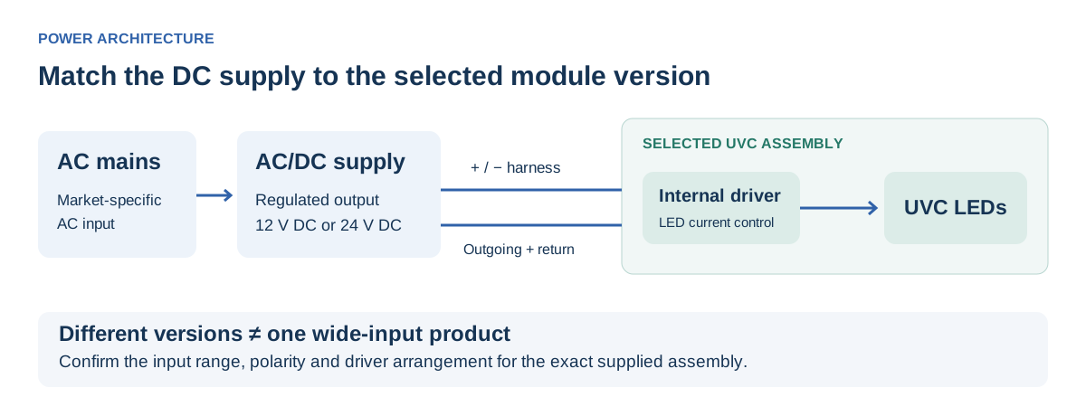
Confirm that architecture for the selected product before choosing the external supply.
Technical Comparison: When Does 12 V or 24 V Make Sense?
Start with the appliance’s existing power system.
| Design condition | Practical selection approach |
|---|---|
| An existing 12 V supply has sufficient capacity | A compatible 12 V module can avoid adding another conversion stage |
| An existing 24 V supply has sufficient capacity | A compatible 24 V module can connect to the existing supply |
| Both voltages are available | Compare current demand, harness voltage drop, supply loading, and integration cost |
| Higher power or a longer harness creates excessive voltage drop | Evaluate a 24 V version alongside a larger conductor or shorter cable route |
| The selected module supports only one voltage | Design the supply around that specified input |
Power and cable length influence the decision, but neither provides a universal switching point. An 8 W module does not automatically require 24 V, and a one-metre harness does not automatically rule out 12 V.
The following Agua Topone examples show why the voltage version remains a separate selection item:
| Model | Published electrical input power | Voltage versions | Integration detail |
|---|---|---|---|
| EC-11 | ≤1.8 W | 12 V DC or 24 V DC | 160 ±5 mm lead with XHB2.54-2P terminal |
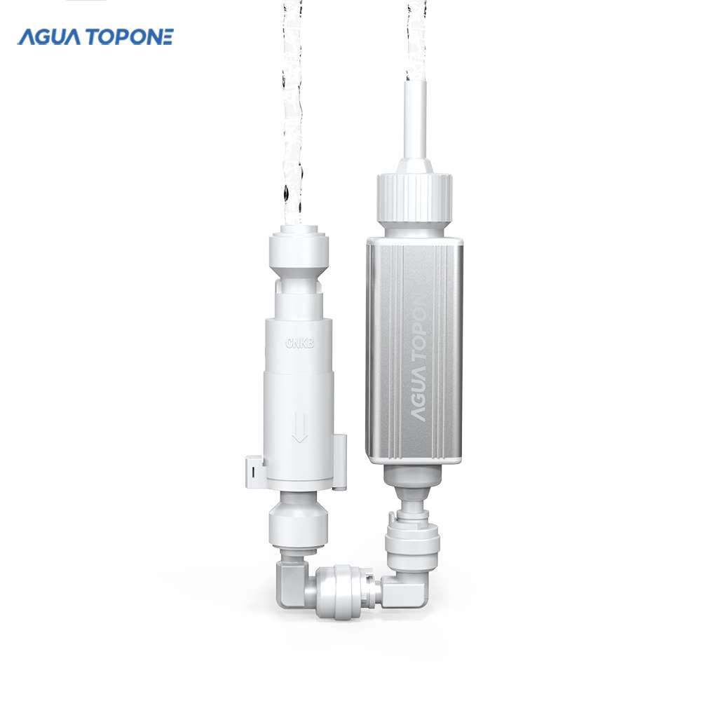
| EC-12 | ≤4.8 W | 12 V DC or 24 V DC | Integrated flow switch; 335 ±5 mm lead |
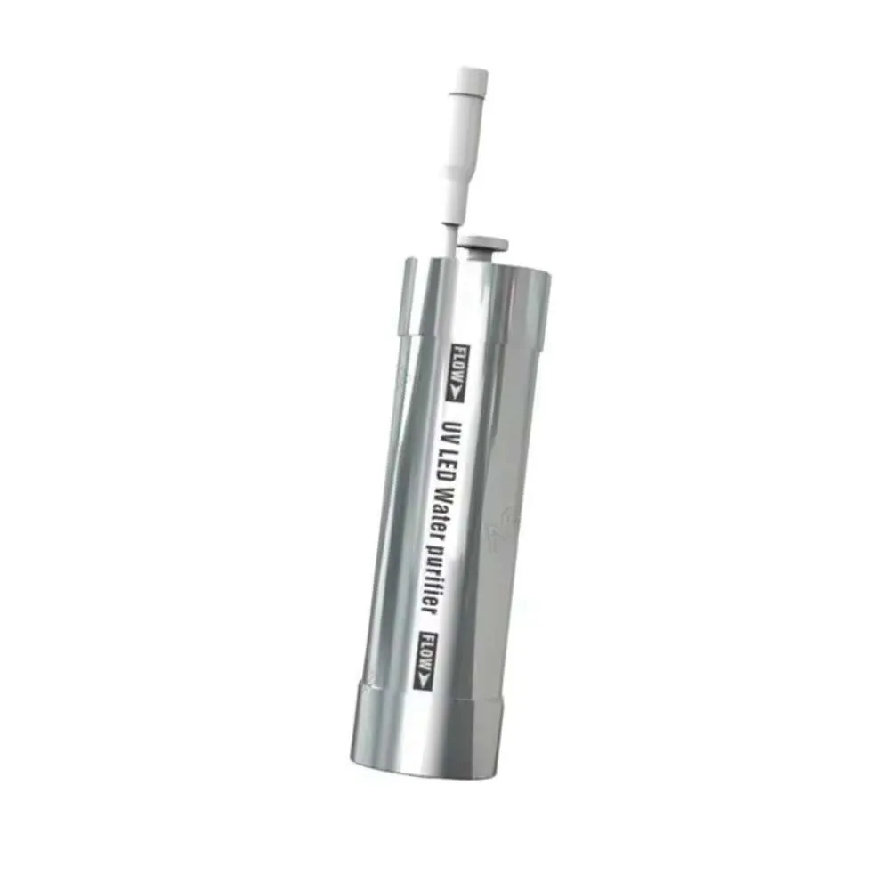
| AGLED-40002 | ≤8 W | 12 V DC or 24 V DC | Flow activation; 500 ±5 mm cable |
Calculate the current from electrical input power
For steady DC operation:
Therefore:
Here, Pin is the assembly’s electrical input power in watts. UVC radiant output, often listed in milliwatts, cannot be substituted into this calculation.
For an illustrative 8 W load:
- At 12 V:
- At 24 V:
At equal input power, doubling the voltage halves the current. These are nominal estimates; final supply selection must account for the actual module’s operating range and startup behaviour.
Check the capacity remaining on a shared supply
A suitable voltage does not guarantee sufficient available power.
The same supply may operate the pump, valves, display, controller, and UVC module. Review the loads that run simultaneously:
Apply this sum to loads on the same DC output. Include conversion losses where additional DC/DC stages are involved.
Then evaluate startup peaks, load changes, and the power supply’s temperature-dependent output rating. A successful test with the UVC module connected alone does not establish reliable operation when the pump starts.
Wiring Harnesses: Calculate Voltage Drop and Resistive Loss
The practical advantage of lower current becomes clearer when the wiring is included.
For a two-wire DC harness with equal outgoing and return conductors:
Where:
- Rloop = total outgoing-and-return resistance, in ohms.
- ρ = conductor resistivity, in Ω·mm2/m.
- L = one-way cable length, in metres.
- A = conductor cross-sectional area, in mm2.
- Rconnections = combined connector and joint resistance in the loop.
The factor of two accounts for the outgoing and return conductors. Once total loop resistance is known, calculate:
Worked example: 8 W through a 0.20 Ω harness
Assume both voltage versions consume 8 W and use a harness with total loop resistance of 0.20 Ω. Using nominal voltage to estimate current:
| Calculated quantity | 12 V design | 24 V design |
|---|---|---|
| Input current | 0.667 A | 0.333 A |
| Harness voltage drop | 0.133 V | 0.067 V |
| Drop as a percentage of nominal voltage | 1.11% | 0.28% |
| Harness resistive loss | 0.089 W | 0.022 W |
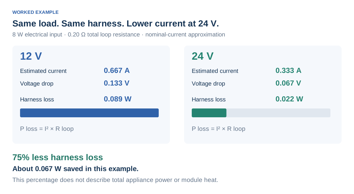
These are illustrative calculations, not measurements of a specific product. They use a small-voltage-drop approximation; actual current depends on the voltage reaching the module and its driver behaviour.
Under these assumptions, the 24 V design produces 75% less resistive loss in the harness:
The absolute saving is approximately 0.067 W. That figure helps put the percentage into perspective: the calculation describes heat generated in the wiring. It does not establish a 75% reduction in module heat or total appliance power consumption.
Select wire size against the permitted voltage drop
A useful design check is:
Use the lowest expected supply voltage, the relevant maximum current, and loop resistance under the intended operating conditions. Also verify the module’s upper input limit and supply transients.
This provides a basis for choosing conductor size. The final wire specification must also satisfy current capacity, insulation temperature, bundling conditions, mechanical requirements, and terminal compatibility.
A longer harness calls for a calculation. If the result is unacceptable, shorten the route, increase conductor area, improve the connections, or evaluate a compatible 24 V version.
Connectors and Polarity: Specify the Complete Connection
A connector that physically fits may still have the wrong pin assignment, current rating, or environmental protection.
Include the following in the harness drawing:
- Connector housing, terminal, and mating-part references.
- Pin numbers and viewing orientation.
- Positive and negative assignments.
- Wire size, insulation specification, and finished cable length.
- Retention and strain-relief requirements.
- Environmental sealing requirements for the installation location.
Latching, polarization, and sealing serve different purposes. A latch helps retain the connection; polarization helps prevent incorrect mating; sealing controls ingress under defined conditions. For example, the JST SM specification describes locking and polarized construction, which should not be treated as a waterproof rating.
If a sealed connection is required, specify the rated assembly and its installation conditions, including the mating components and cable seals.
Verify polarity before energizing the sample. Reverse-polarity protection, where provided, must be documented for the selected module and operating conditions. Carry the approved pinout into production so that electrical compatibility does not depend on wire colour alone.
Operational Control: Coordinate Power with Water Flow
The electrical specification should explain when the UVC source operates.
| Control arrangement | What the OEM needs to define |
|---|---|
| Integrated flow switch | Activation threshold, stopping behaviour, and required power availability |
| Host-controlled power switching | Startup timing, switching capability, and dispensing sequence |
| Dedicated enable input | Logic voltage, polarity, timing, and default state |
| Status or fault output | Signal type, meaning, and appliance response |
AGLED-40002 lists a startup flow of >500 mL/min. EC-12 also incorporates a flow switch, with the activation threshold established for the quoted configuration. Apply each model’s own control specification. AGLED-40002 specifications, EC-12 integration details.
Check both the highest intended dispensing flow and the lowest normal draw. If the appliance dispenses below the module’s activation threshold, the control arrangement needs to be resolved before approving the design.
Where PWM or another external control interface is required, establish its availability and electrical limits with the supplier. Any reduction in UVC output must also be evaluated against the treatment requirements at the intended flow and water conditions.
During prototype validation, test the complete sequence: dispensing starts, flow changes, dispensing stops, and power returns after an interruption. The approved configuration should define the appliance response to each event.
Pre-RFQ Checklist for OEM Engineers and Procurement Teams
A useful RFQ connects the power requirement to the actual appliance.
| Information to provide | Details that support selection |
|---|---|
| Application and proposed model | RO system, dispenser, drinking-water terminal, or another appliance |
| Water operating conditions | Minimum and maximum dispensing flow, pressure, temperature, and upstream treatment |
| Water quality and treatment target | UVT with measurement wavelength and path length, relevant water-quality data, and target dose or organism reduction |
| Available supply | DC voltage, output rating, other connected loads, and external-adapter requirements |
| Harness and connector | Cable route, length, pinout, mating connector, and environmental exposure |
| Control sequence | Flow activation, power switching, enable input, status signals, and fault response |
| Mechanical integration | Installation space, mounting, water connections, and service access |
| Market and purchasing requirements | Target market, required documentation, sample quantity, and expected production volume |
The sample order should turn these details into a reproducible configuration: a named module, a defined voltage version, an approved harness, and an agreed operating sequence.
For an Agua Topone OEM project, send your supply details, proposed model, and wiring sketch. These provide a practical starting point for reviewing the voltage version, connection, and control arrangement together.
Frequently Asked Questions
Can a 12V UV water sterilizer run on a 24V power supply?
Use the input specified for that module. Applying 24 V to a dedicated 12 V version exceeds its rating and may damage it. Select a 24 V version or engineer a suitable regulated DC/DC conversion stage, including its capacity, losses, and startup behaviour.
Does a 24 V module disinfect more effectively than a 12 V module?
Supply voltage alone does not establish disinfection performance. Evaluate the specific module’s UVC output, reactor design, flow, water conditions, and applicable test results. The voltage comparison in this article concerns electrical integration.
Can I use a power supply with a higher current rating than the module requires?
For a module designed for regulated constant-voltage input, the supply’s current rating describes its available capacity. The module draws current according to its load. A higher current rating can be acceptable when voltage, regulation, protection, and the complete electrical specification are suitable.